|
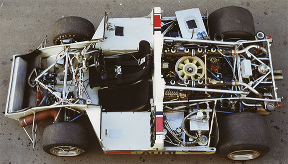
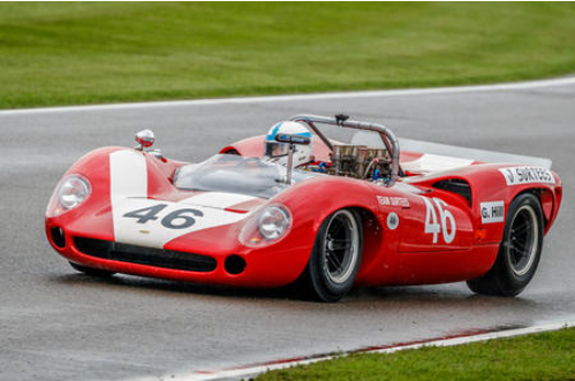
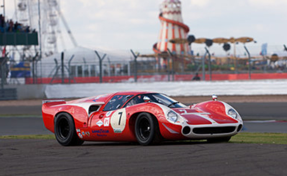
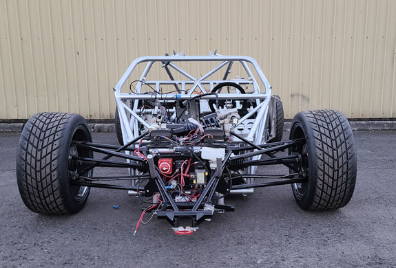
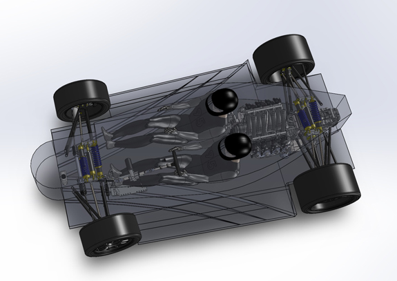
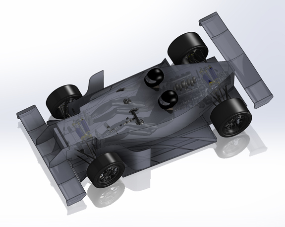
05/04/20 The whole point of experience and learning is that we put it to a good use. Learning what works and what doesn't is only useful if we leverage it to build and do things that work better. Now, of course, 'better' is a subjective term (that in itself is a lesson but I digress). So, this brings me to the new project - the D8. It is based on everything I've learned so far, both about building cars and the nature of the car business. As well as where I'd like to be in it. The basic concept is simple, and on the surface it may seem that it's been done many times... a CAN-AM type car for the road and track. Raw, focused, prioritising performance and intensity of experience over convenience and comfort. Something you'd use only occasionally, when everything is right, but then really USE it. Countless examples already exist - Ultima, RCR, and several dozen other companies have done their versions. So what can I do 'better'? To me the late 60's - early 70's CAN-AM and Le Mans sports racers are the perfect concept - compact, powerful, emotional. Many were beautiful as well. Of course racing was still a 'blood sport' back then and safety was not a high priority. Likewise aero was only in early stages. Today we can and should do better on both. But can it be done staying true to the concept?
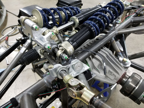
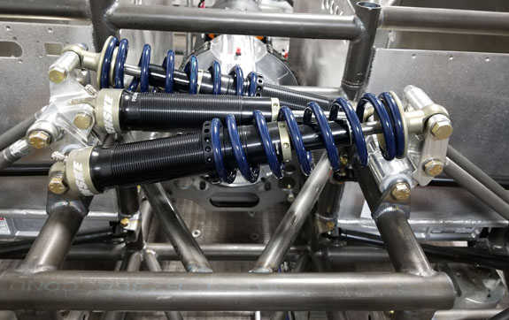
Of course many replicas exist, and have for decades. Some merely resemble the original cars, others have bodies made in molds taken from original bodywork. But improvements in chassis have been modest at best, and nil in aero. Which is where I want to do something different. Over the last 12 years I've learned a lot about suspensions, have extensively experimented and tested various configurations, and found what works and what doesn't. My latest Gen III D2 setup is the culmination of all that effort, and I want to use it here.
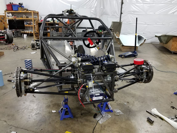
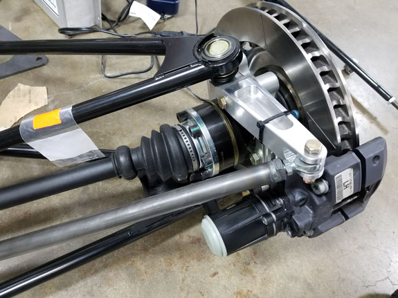
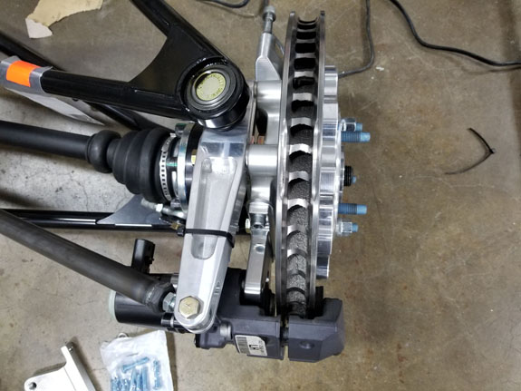
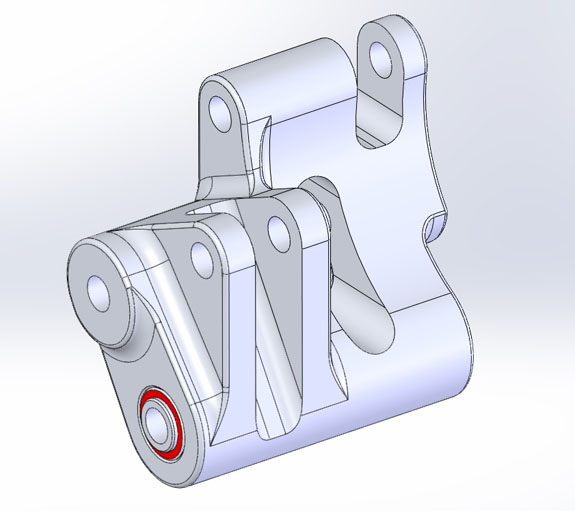
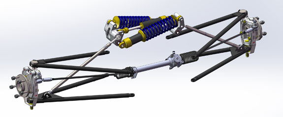
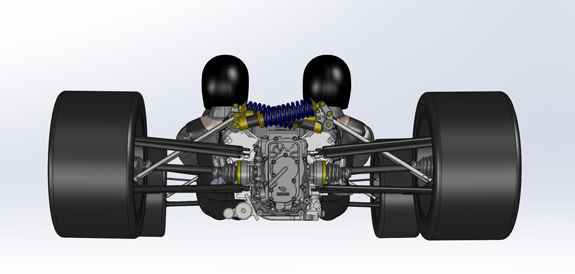
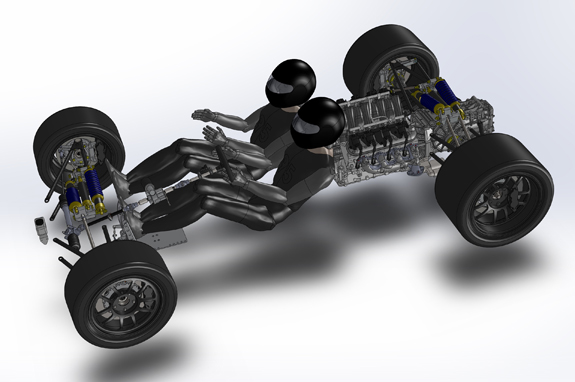
Some of the benefits include control over motion ratios, wheel rates and damping throughout the range of motion. Also geometry - notice camber compensation in roll on the picture below:
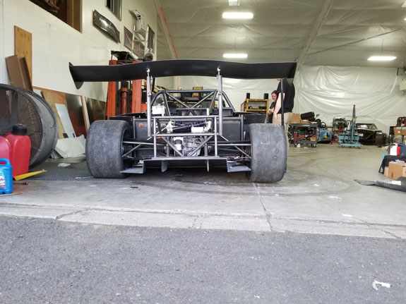
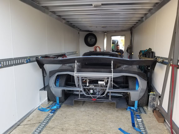
This makes the inside tire do its fair share of the work, instead of being a 'throwaway' as it is in most conventional designs. The payoff is as much as 50% increase in mechanical grip. Aero is another aspect that I want to improve, but I'll go into that later in the post. First, some packaging. I like the wide stance of the 917 and similar cars, but it has to be manageable. The D2 at 81" wide has proven to be a bit much, requiring custom trailer with 83" between wheel wells.
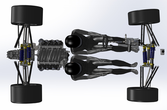
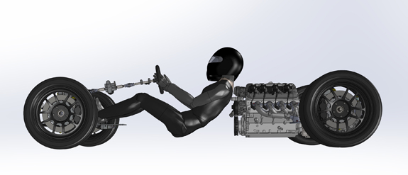
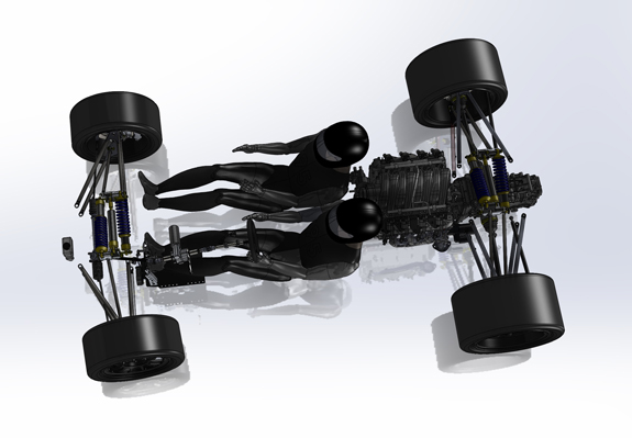
For this reason, I've concluded that 78" is the maximum usable width for what I want to do. Wheelbase is next. CAN-AM cars range from 90" for 917 to 95" for T70, GT40, etc. They keep the wheelbase short by putting the driver quite a ways forward - which for safety I'd rather not do. But, a quick study shows that 95" is achievable with LS3 powerplant and keeping the driver essentially in same position he is in the D2. Can be shortened even more for 917 dimensions, but at the expense of halfshaft angularity.
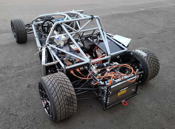
The D2 GIII suspension transfers over unmodified. The overall length should be in the 155" range (same as a Miata). Height about as tall as the Miata hood :). And of course 10" wider. Total weight should be doable at 1,600 lbs or so. Base LS3 is 430hp/420lb-ft which should be plenty, but experience tells me people will want more just because. Of course an electric variant using Cascadia components (derivative of D2EV) will be an option, with about 900hp and 200+ mile street range. So far so good. Next, aero. One challenge is that for a streetable car a 4" ground clearance is desireable (3" can work for the more hardcore drivers). This makes it difficult to generate ground effects downforce. And, if we were to stay true to the originals, external wings and appendages are really not preferred (but possible). I have a few ideas I'd like to explore, so I've started on some exploratory CFD. This is just to evaluate shapes and how components and design elements interact. I wanted to see how it would work with and without wings (with no bodywork at first, later through-body airflow will be similar to the D2). I do all runs at 100mph for consistency and because it's a relevant speed. In clean air the wings genearate about 300 lb downforce each. However the presence of the car degrades that significantly.
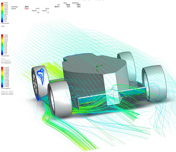
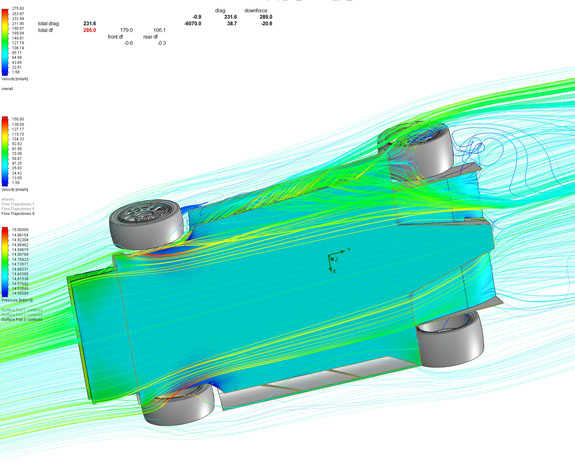
The key concept I want to explore is creating an 'air skirt' at the sides to 'seal' the underfloor. This is similar to the current F1 aero philosophy in some ways, pushing the air out to the sides.
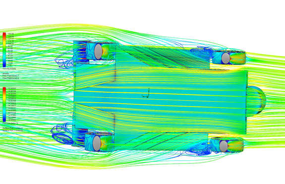
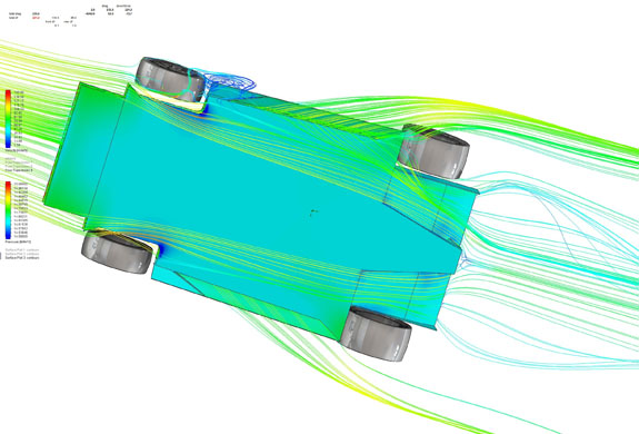
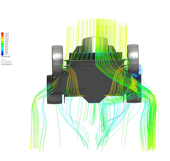
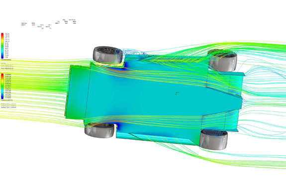
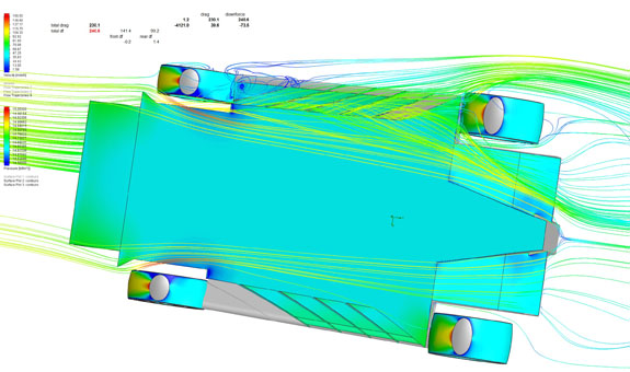
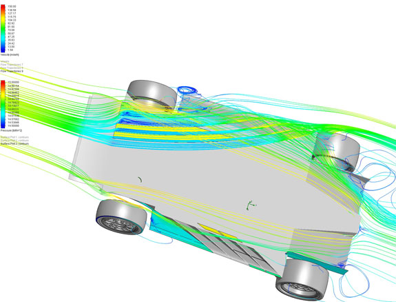
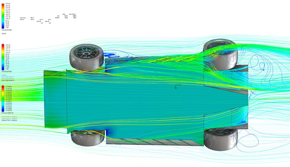
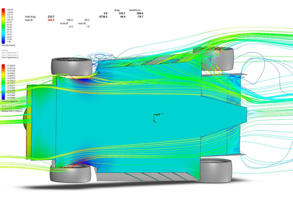
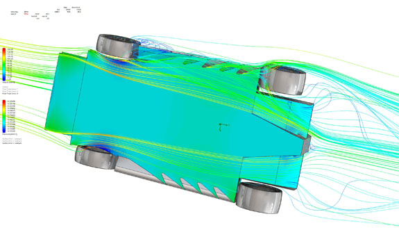
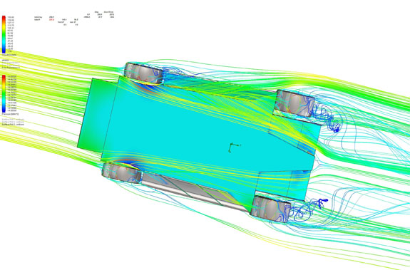
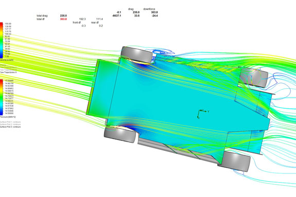
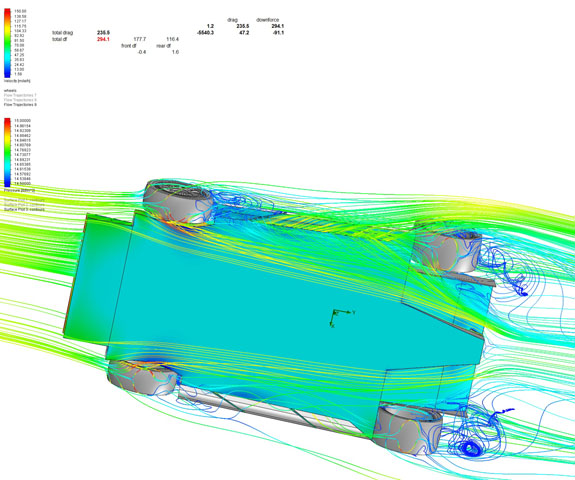
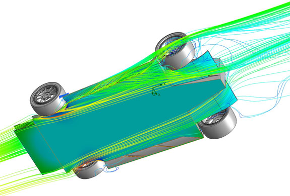
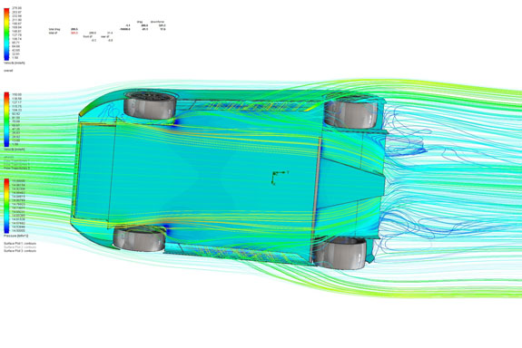
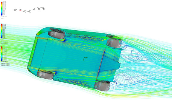
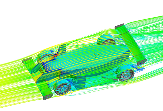
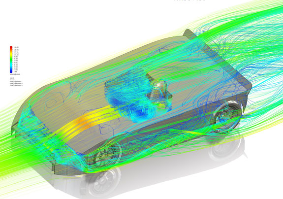
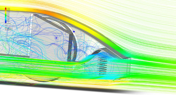
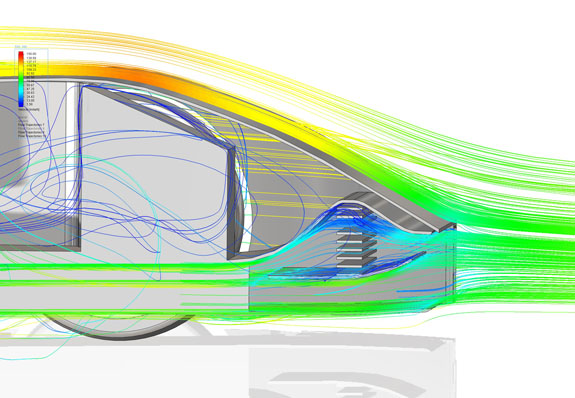
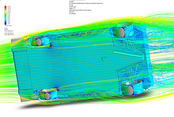
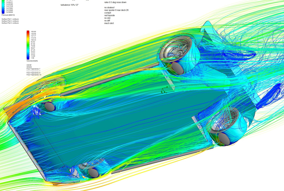
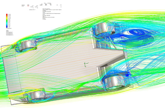
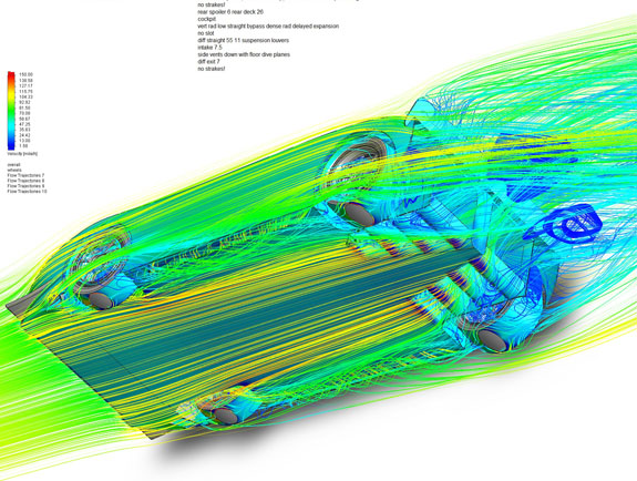
Initial runs are promising! There is a lot to learn here. CFD is a methodical and incremental process. Change one thing at a time, simulate, record results, repeat. Fortunately my new AMD Ryzen workstation rips through the simulation in a lot less time than the old system, and more importantly I can continue to do work with no apparent performance penalty while the simulation runs. This means I can do two-three runs during the day and one overnight, instead of just the overnight that was practical before. Makes things go a lot quicker but still it's a process. If this proves to be as effective as it promises to be, I may decide to file a patent application - I have one year from initial disclosure to do it. I'll go into the results in the next post. In the meantime, yes I'm looking for lead customers. Ideally would like to have 3 or 4 to start. With 95" wheelbase we can do a number of existing replica bodies - no need to reinvent the wheel. Or, custom designs are possible as well. Think of it as a full-size RC car which you can experience first-person :) 05/10/20 CFD can be both frustrating and exciting. Fundamentally, it's a methodical task. Change one thing, simulate, record the results, learn, come up with next thing to change, repeat. Fortunately the computing technology keeps advancing, and with the latest AMD Ryzen system what used to take 12 hours (tying up the whole thing) now takes 3-4 hours and I can still use it for other tasks. So gratification is a fair bit more 'instant' now, but it's still a process. In general, I've found that aero is often non-intuitive, except in hindsight. So many times I've looked at the results and thought 'I should have predicted this', but of course I didn't. Makes sense now though. And so it is with the D8 study. I've now run literally over 3 dozen iterations, all without wings. I'll come back to that in a bit. But, the downforce results have ranged from 152 lbs to 327 lbs (all at 100mph and 4" rideheight, and including lift from wheels/tires). The changes have been subtle and had to do mostly with shape of 'strakes' and inlet/outlet conditions. I was surprised more than once. Without going into too much detail, I'll just post a few sample pictures and let everyone interpret them for themselves :)
This is a mere fraction of the total. Just keeping track of what was tried and what the results were is a major challenge in itself, but I do have the method now. I'm happy to say I've learned a lot in the last week, and am very encouraged by the results. The next steps will be to add a simplistic bodywork and see how that affects things. Earlier I've mentioned wings. In free air, without car nearby, the wing shape and size we've been using produces about 300 lb downforce and 40 lb drag at 100 mph and AOA just short of stall/separation (it's an Eppler 420 airfoil of 13" chord, for anyone curious). So two wings would be 600 lbs. Once you put a car in the vicinity, that number drops dramatically. Effective on-car downforce is more like 100 lbs for the front and 200-250 for the rear. But, for reasons of aesthetics and others, I would like to try and avoid wings altogether on the baseline car. For reference, before we added dive planes, tail spoiler and 'barge boards' to the D2, the entire car with front and rear wings was producing about 200 lbs downforce at 100 mph. We eventually got it up to almost 700 with the above bits. So, being in 300-350lb range WITHOUT wings is pretty exciting. To me at least. Keep in mind that most wingless cars produce net lift. But this is just an in-progress update. Much more to come. And yes, there are many things happening on the D2 front, and others, as well. Separate posts coming soon. 05/11/20 Sometimes this is just FUN :) Tweak a few things, have expectations, partial results a bit short, and then score! What can I say, I'm still a kid at heart. So as I mentioned, the next step is bodywork. Still pretty idealized, just building from the ground up.
The bodywork definitely has a major influence on airflow around the floor. But the basic architecture still holds which is reassuring.
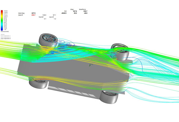
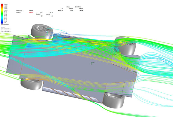
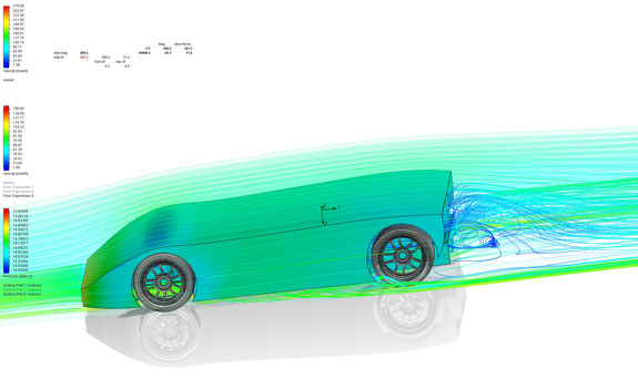
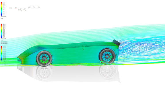
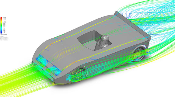
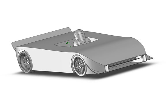
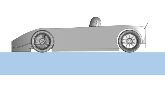
I may have mentioned that there are many different ways to make downforce, and that the entire car has to be consistent with the approach. One of the more powerful is the 'hollow body' downforce, which basically works like a wedge pushing the air to the outside and up, creating a low pressure under the entire body shape. Aero is a game of square inches, and bodywork has the most. Hat tip to Gary Wheeler, the inventor of the Wheeler VG, for making me see this. Gary worked for Dan Gurney back in the AAR days and is responsible for quite a few advances in both car and airplane aero. Hollow body is quite different from ground effect (Colin Chapman style). Here's an example. First picture is the D8 basic body shape. Second is the same thing, with the mere addition of a 5" spoiler.
The big difference is in what happens behind the car, and by extension what happens everywhere. The numbers are dramatic. Before, total downforce 391 lbs, of which 360 is front and 31 rear. Looking at pressure distributions confirms why this is so. Then, with just the addition of the spoiler, the result is 690 lbs with 368 front and 322 rear. Again looking at the flows and pressure distributions it makes sense.
The spoiler itself is not what does it. Everything that's in place for it to work, is what does. The spoiler just allows it all to do its thing. It's the final piece in the puzzle. But every piece matters. Everything is connected to everything else, and no element can ultimately be taken just by itself. And that's what makes it FUN :)
5/21/20 OK, this phase is almost done. You may recall the first goal was to establish packaging.
Next, I set out to see what aero solutions would work best with the form factor, keeping in mind that I want to be able to support CAN-AM replicas on this platform. Even with that, I started from the ground up to set some reference points and evaluate key concepts, as detailed in the earlier posts.
Much was learned and then it was time to add bodywork and see what effect various features have.
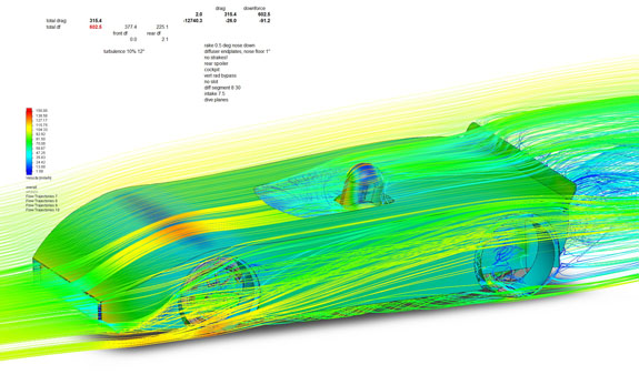
I have now completed over 50 CFD runs and have learned a tremendous amount. Each run takes anywhere from 3 to 12 hours, so this is where having your own setup really helps - I couldn't afford to pay somoene else to do this for me. A special thanks to Arron, a senior aerodynamicists with vast experience in motorsports including top F1 teams, for providing feedback and input. As a result of all this, the configuration in the second picture below (without wings) has more than double the downforce of the first one, and virtually same drag.
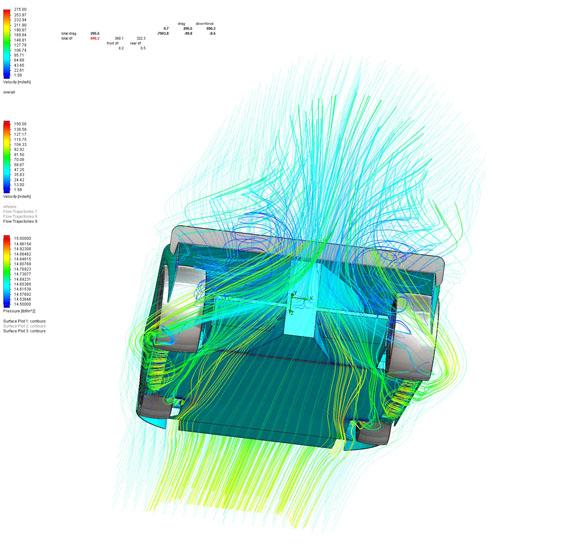
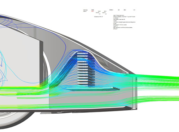
There were countless steps, like experimenting with diffuser angles, widths and side plate shapes. Dive planes. Skirt ramp angles, slot widths, intake and ramp exit geometry. Spoiler height. Vent on top of the nose to relieve the low pressure (didn't relly help, just shifted the lift elsewhere). And so on. One key item has been provision for cooling. This has to be worked into the overall architecture from the start, rather than done as an afterthought later. I tried many configurations. Some are presented below without comment, everyone can inerpret for themselves :)
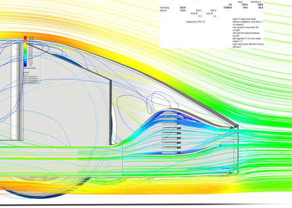
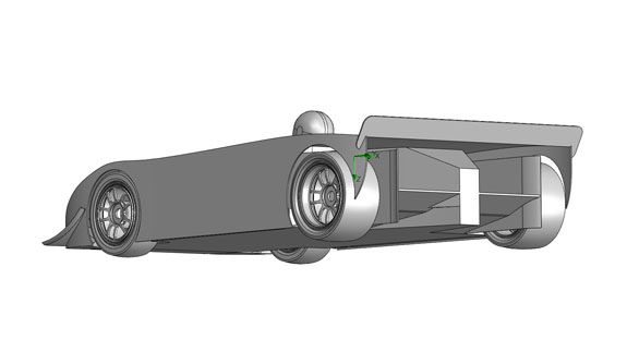
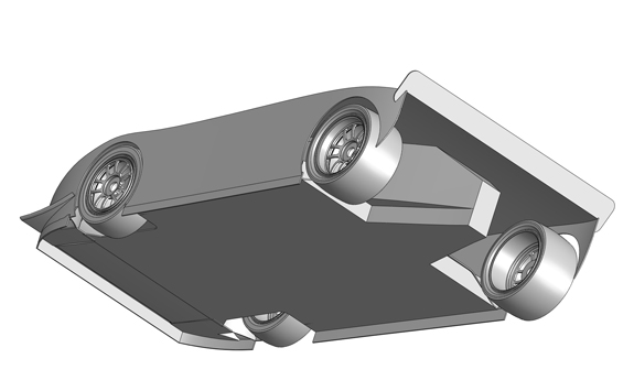
Now that I have all the necessary data I can make informed decisions going forward. This is what the basic architecture looks like now.
As a final sanity check, I did a CFD run without the fancy air skirt and ducted radiator, instead using the traditional CAN-AM flat floor and top-exit radiator. The differences in flow and pressure distribution are obvious.
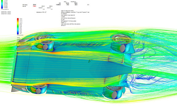
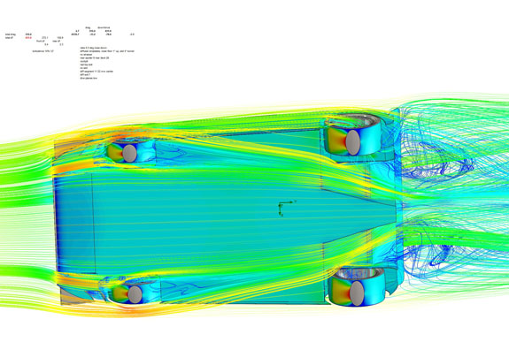
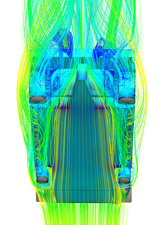
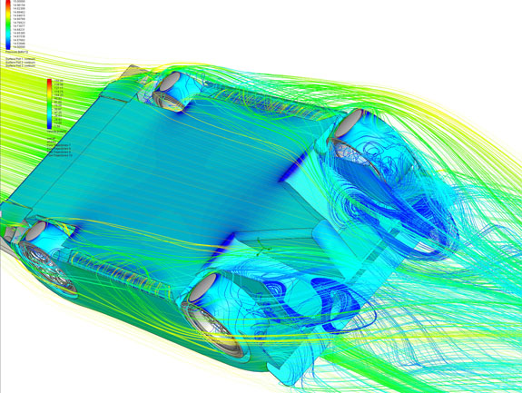
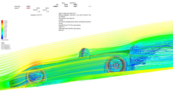
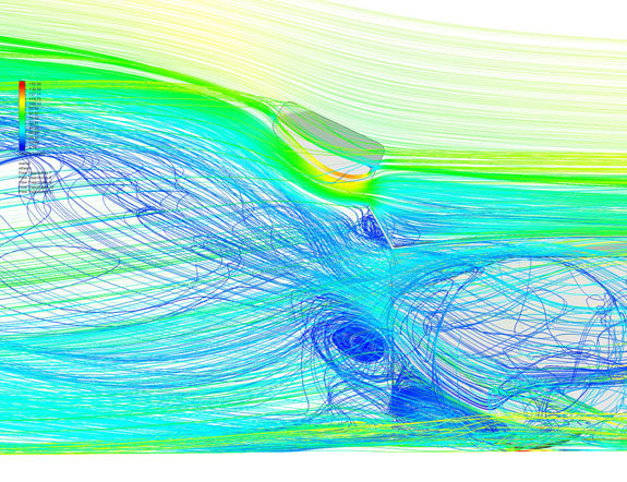
The numbers are satisfying as well. The 'traditional' setup is actually pretty decent, at 100 mph producing 431 lb downforce 315 lb drag. My configuration with air skirt and ducted radiator makes 729 lb downforce and 333 lb drag at same speed. With a standard 430hp LS3 the top speed should be around 160mph (producing 1,800 lb downforce). The 900hp electric version should top out just above 200 mph and should be making around 3,000 lb downforce at that speed. This tells me how I should set up the gearing :) My suspension bellcrank geometry will get a workout as well. Everything is connected to everything else and it all has to work together. Indications are that I'm off to a good start. Next, chassis design. 5/29/20 Foremost, I'm an architecture guy. What this means is that I always look at the big picture, try to understand all the pertinent parameters, and only then dig into the details. This set of aero experiments has been about understanding the big picture. I will explain. First, as a matter of big picture, it is useful to keep in mind that while we do CFD in a 'car-centric' coordinate system, with car 'stationary' and air 'moving past', the opposite is true in reality. The car-centric view is just for convenience of computation. In reality, the air and ground are just sitting there and the car moves through/over them. All the simulations are carried out using Solidworks Flow Simulation 2012, on a AMD Ryzen 9 with 64G RAM. The runs are at 100mph, sea level, 20C, with moving ground and rotating tires. In all my images, the surfaces are colored by pressure (blue is low, red is high), while all flow lines are colored by velocity (blue is near zero, red is 150 mph, green is 100mph which is road speed at which all these simulations are run). What this really means is that blue air is dragged along with the car, green air stays more or less put or is dragged slowly, and red air is actually pushed in the opposite direction of car travel. This also means that blue air, while it may appear to swirl, produces about as much force on the car as air from the air conditioner vent. So while it may look like 'turbulence', it should really just be considered air that is still relative to the car and travels with it. You will see that in most pictures, so keep it in mind. Look at the image below and internalize this, it will help you understand everything else.
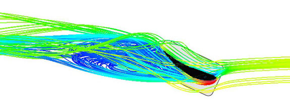
As I've said earlier, there are different ways to create downforce, which for cars come down to two main approaches - what I call 'airfoil' and 'hollow body'. Technically there is also a third, 'external devices' like splitters and wings, which can work to an extent separately or as part of either of the main two. Airfoils are great, when you can make them work. They are extremely efficient and generate a lot of downforce with very little drag, when operating in their optimal range (more on that later). The downsides are that they are extremely sensitive to shapes, angles of attack, entry/exit conditions, and surrounding obstructions. Interfere with the delicate flow balance and the airfoil is instantly useless. I'll come back to this image later, because it was generated for a purpose, but it illustrates what an airfoil shape is and what happens when it's not happy.
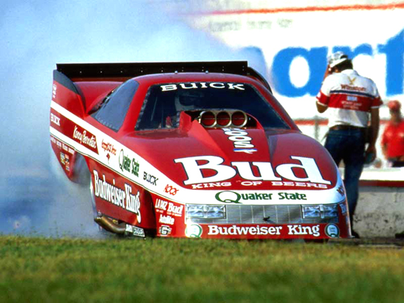
The black shape is the airfoil itself, an Eppler 420 profile that we use for our wings (originally developed for gliders). It works beautifully up to about 12 degrees angle of attack (AOA). At 30 degrees, pictured here, not so much. Here it generates 30% less downforce and more than double the drag that it does at 12 degrees. More (angle) is less (effectiveness), with lots of caveats. It is also quite hard to make a real car look and work like an airfoil. There are wheels, occupants, engine, suspension, cooling, and so on. The group C and ground effects F1 cars did manage to make about 1/4 of their overall width look like airfoils, and the results were impressive with as much as 5:1 L/D (lift/drag) ratio, helped by proximity to ground and mechanical side skirts (same airfoil in free air would generate a fraction of the forces). Super sensitive to setup and rideheight though. Making airfoil downforce is all about managing the flow (i.e. pressure gradients) and keeping it attached. Entry, exit, compression, expansion, and interference are crucial. Gentle transitions, limited range of workable angles (as shown above). A key aspect is that topside flow has to be properly merged with under-car flow, which requires a low deck and just as much attention paid to what's on top of the car as what's on the bottom. The other approach is 'hollow body'. Here is a great example, Kenny Bernstein's 'Buick' designed by Gary Wheeler.
It produced 10,000 lbs downforce at 270 mph, which you wouldn't expect by just looking at it. When Gary first told me about it, it took me a bit of mental gymnastics to understand how this is possible. The key to 'hollow body' downforce is creating a low pressure area behind the car and letting it extend inside/under the bodywork. The last part is critical, because if low pressure is only behind the car all it produces is drag. If low pressure extends from the back forward and under the car, the downforce is then the difference between total pressure on the outside and the total pressure on the inside. Bodywork has a lot of square inches, so even a small pressure differential can produce big numbers. This is pertinent to the diffuser discussion later. The 'hollow body' architecture requires a wedge shape with a high rear deck (the opposite of 'airfoil'), and generally keeping air out from under the car (also the opposite of airfoil). There does have to be a path for the low pressure behind the car to extend under it, which I'll illustrate later in the post. In all, this approach is a lot more realistic for regular shaped cars, which makes it useful to understand. You may recall from earlier posts that the primary innovation in the D8 is the 'air skirt', which seals the underbody at a streetable 4" rideheight. This is simply just one way to do it, and streetability is the reason. To illustrate, I first ran a configuration with no 'air skirt' and 4" ground clearance. You can see the flow coming in from the sides. It produced 431 lb downforce and 315 lb drag, for a 1.4 L/D ratio. Not too bad actually, owing to its wedge shape and the presense of a diffuser.
Next I ran the exact same configuration with the 'air skirt'.
This produced 732 lb downforce and 326 lb drag, for a 2.25 L/D. The distribution was also more favorable, with more rear force (but still favoring the front). As another reference, next I tried the air skirt variant with no diffuser.
This was 612/309, for a roughly 2:1 L/D. So the diffuser does make a difference, but it serves to help 'feed' the low pressure area forward, rather that managing expansion of underbody flow as it would on an 'airfoil' design (more on this below). I say this because grossly over-expanding the diffuser, to where much of the flow was detached, produced better overall results. A final reference point is a configuration with a mechanical air dam and side skirts, and no diffuser.
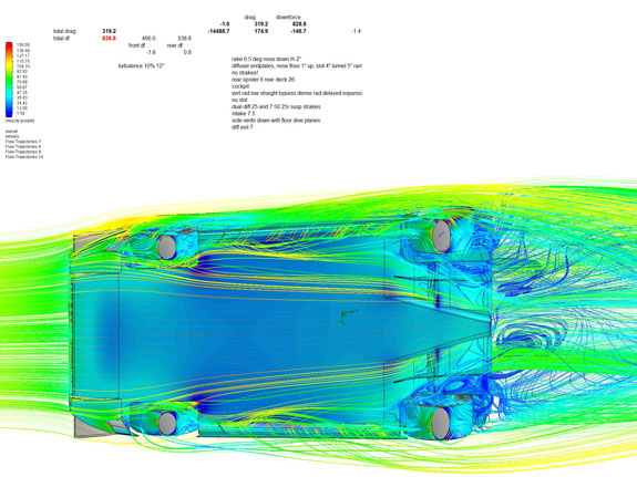
You can see that underbody flow is now all blue (very slow), with only a bit of hig-speed air sneaking in behind the front wheels. The numbers are 605/315, almost identical to the air skirt no diffuser configuration. Which shows that the only 'magical' thing about the air skirt is the fact that it effectively seals the underbody without a physical piece hanging down and rubbing on the road. Definitely a nice feature for a streetable LeMans replica, but reality check says there are other ways to get the same thing. The latest configuration in particular illustrates the 'hollow body' approach, and shows that even with air skirt and diffuser, this is a 'hollow body' architecture at heart. So things that would apply to an 'airfoil' design would likely not apply here. How? Read on. Next I started experimenting with the diffuser. In 'airfoil' design, the rule of thumb is that anything beyond about 11 degrees will separate and 'stall', losing effectiveness. However the function of the diffuser in a 'hollow' design is to allow the low pressure behind the car to extend underneath it and draw the air out. So I tried a lot of configurations and angles, from 11 to 50 degrees, as well as radical concave and louvered shapes. First picture below shows difference between a radical 'concave' diffuser and the 11 degree baseline. The concave version worked significantly better, even with suspension in the airflow, producing 740 lb downforce vs 627 for the 11 degree version.
Literally dozens of runs later I determined that 45-50 degrees worked best, as did some (but not all) louvered/multiphase configurations. The best performance was 762/334, or 2.28 L/D. Keeping in mind that this is a car with 4" rideheight and no wings, I'm actually quite happy! For a streetable configuration this is more than adequate. But, what if we wanted to take it to the track? The next step was to drop rideheight to 2". Immediate improvement, resulting in 828/319, a 66 lb (8%) gain in downforce and an actual drop in drag, for L/D of 2.59. Still, not overly sensitive to rideheight which is good. Note the darker blue underbody vs earlier pix.
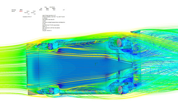
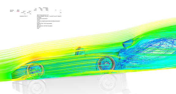
But what if we were willing to add a wing? Currently the downforce is front biased, and we actually want a rear bias for stability. Wing would help that. And this is where it gets fun, because we get to see how things interact. First, the underbody pic. Compare to that above and notice a lot more dark blue everywhere. In fact, the addition of a wing makes the same body pieces (floor, body, wheels) produce 1,038 lb downforce and 361 lb drag without the wing counted in. So, adding a wing made the OTHER parts produce 210 lb more downforce, along with 42 lb more drag. The wing itself adds 205/107, for a grand total of 1,243/468, a 2.65 L/D.
The real fun part is in how the wing interacts with the spoiler. The airfoil is actually at 30 degree from horizontal but there is no separation!
Recall the picture from the beginning of what happens to the wing at the same angle in free air. This is why I ran this simulation, as another reality check.
With the presense of the body and the spoiler, the wing becomes a slotted flap rather than a separate wing. And with that, it becomes sensitive to position and alignment. The runs I'm reporting were done with just a gut-feel guess as to where it should be. Shifting it forward, maybe up, maybe messing with angle, is likely to produce a lot of interesting results. Especially keeping in mind how much it affects the body/underbody! I'll play with it later. The key point is that in free air, all that the wing is capable of is about 300 lbs downforce. But adding that same wing to the car resulted in a 415 lb increase in downforce, because of the interactions. For now, the aero experimentation is done. I have a good feel for what does what, and can now prioritize the packaging solutions to reflect this knowledge. More to come.
If you find this site useful or interesting, consider supporting it with a paypal donation in the amount of your choosing to dp@dpcars.net
|
