|
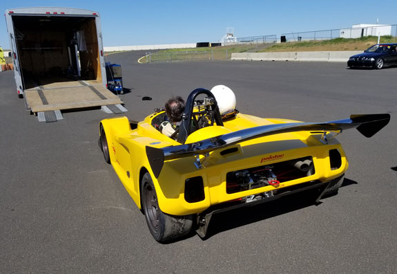
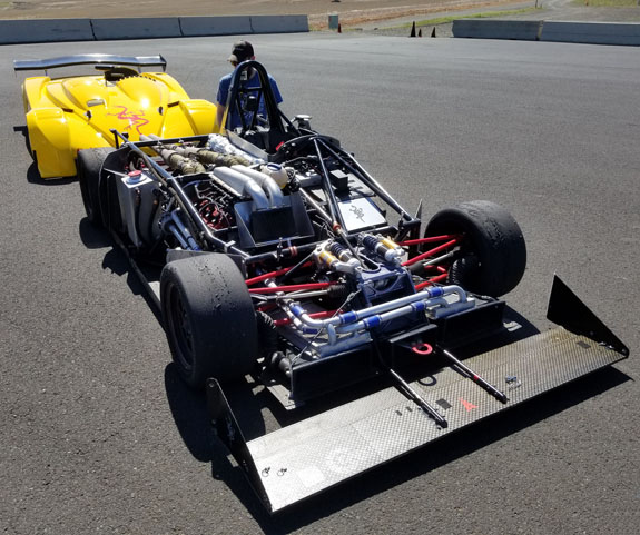
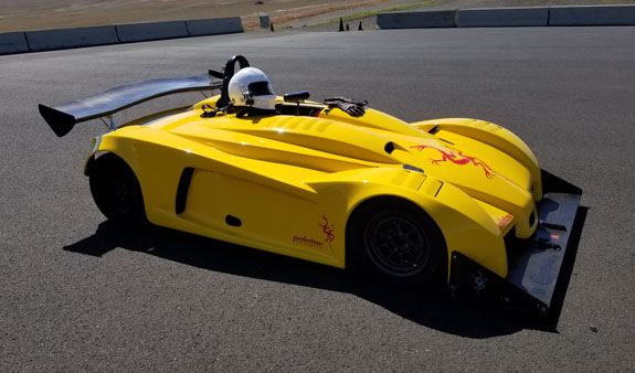
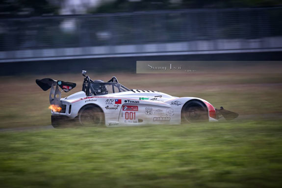
5/13/18 Time for a new blog. The D1 has played a central role in my car design adventures, from being the initial motivation to go down this path in the first place to (for now) holding the most Pikes Peak podiums of any of my designs (D2 may have something to say about that soon). Over the winter we have finally rebuilt the original Hartley V8 in Neil's car, after more than 100 hours of track time. Today was the car's first outing with the fresh motor, new rear wing and fresh paint.
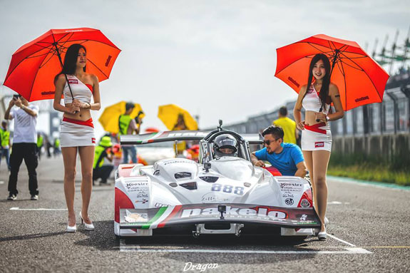
For a custom V8 producing over 400hp from 200 lbs of alloy the engine has been remarkably reliable, but it's not immune to glitches. In this case, a set screw holding a gear to a shaft had backed out and caused all kinds of havoc inside. Fixed now. In the meantime, Rodney's Pikes Peak car is now in Taiwan and enjoying the celebrity life.
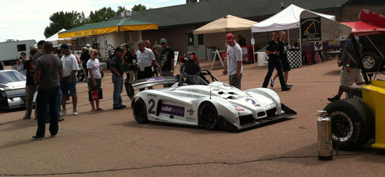
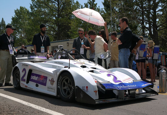
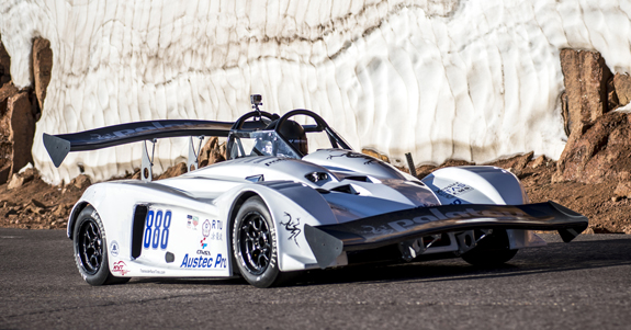
I've learned a huge amount from the evolution and testing of this design. This is definitely going to continue. 09/22/18 We have a lot of development to do over the winter and some of it has to do with aerodynamics. I try to leverage everything I do across as many designs as possible, and while the D1/D4 uses a very different overall aero architecture from the D2/D5, I'm hoping some things will cross over. On the D1, we have tried a few approaches so far: no front devices with a small rear wing, front splitter with a double element rear wing, with and without a front wing (Pikes Peak 2012) and front wing with a bigger single element rear wing (Pikes Peak 2016/2017).
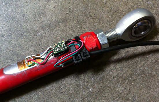
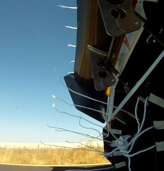
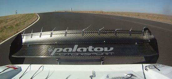
Quite a few things have been learned from this. In 2012 we instrumented the car with strain gages on pushrods and did quite a bit of physical testing of various configurations.
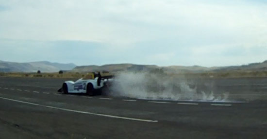
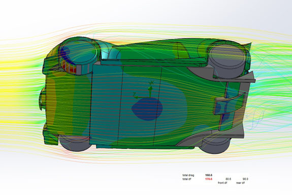
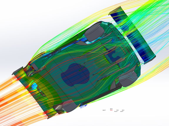
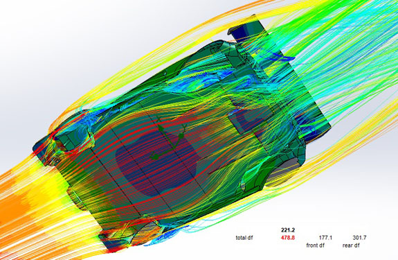
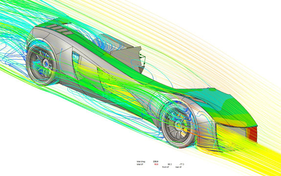
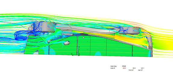
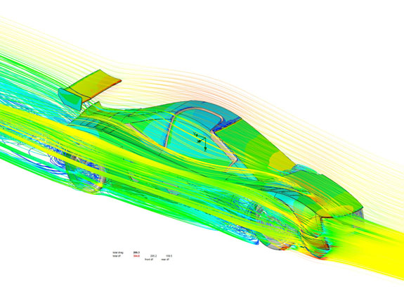
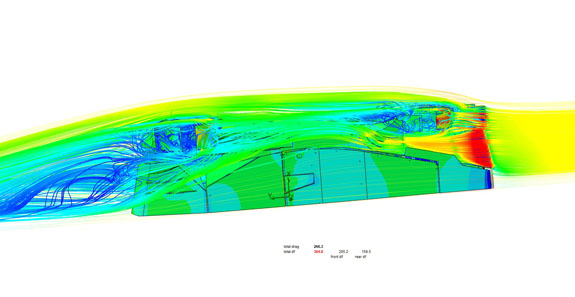
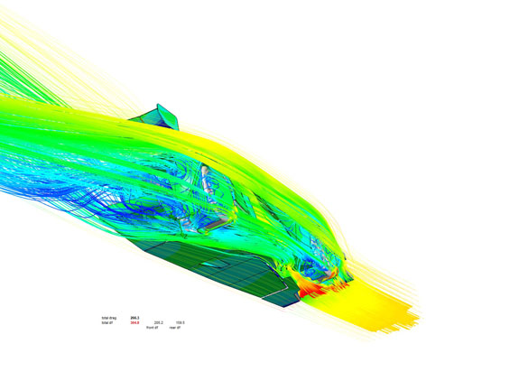
The last picture above is not smoke - we put a line of chalk powder on the ground and drove over it at 100 mph. That same year we got Solidworks Flow Simulation CFD package, and figured out how to set up the simulations so that the virtual results closely match the real world data, in several very different configurations. The thing to keep in mind with CFD is that it is still a simulation, so we treat it more as an extra insight and input into the design process rather than an absolute reference. The numbers are used for two purposes: one is to make sure they're ballpark realistic, just as a reality check on the setup and analysis. The other, primary purpose, is for A-B comparisons when making a single change. This is key - have to make one change at a time to see what effect it has. Which takes a lot of discipline since each run is 7-8 hours. So CFD for me is a weeks-long process, making a change at night and analyzing the results in the morning. All runs are made at 100 mph since that is a very relevant track speed, where aero starts to matter and some actual fast corners and crests are taken in that range. As a side note - the numbers below may seem low compared to what you see being claimed online. I've seen 1,600 lbs of downforce being claimed for a wing that is smaller than the one we use on the D1. The thing with such claims is that they are impossible to prove or disprove, because most often even the people making the claim don't have the instrumentation (wind tunnel or strain gages) to actually measure it. But some simple questions can often give you an idea of realism - the most basic one being 'at what speed?'. You'll be surprised at how often that question just draws a blank stare. Since aero loads vary with the square of speed, that is a very fundamental thing to know. Our wing that makes 200 lbs of downforce at 100 mph would make 800 lbs at 200 mph, but the car would almost never see that (stay tuned for the 'almost' part ;) ). I choose to quote 200 lbs because it's relevant and useful to someone trying to actually tune one of our cars for driving on a real track. It took a bit to figure out how to keep track of all of it, too, and I've settled on a combination of spreadsheet and series of pictures, with saved views, for each run. Some examples below - streamlines are colored by velocity, surfaces colored by pressure. Note particularly the size of low-pressure area on the floor and the progression from 175 lb of calculated downforce to 478. The flow lines are just as educational.
As I mentioned the D2 is a very different architecture - while D1/D4 utilize a wide curved floor with the low point just behind front wheels (designed this way to reduce pitch sensitivity with short wheelbase), the D2 has an almost open-wheel setup with a narrow, long and flat floor followed by a diffuser. Unsurprisingly a D2 makes less downforce than a D1 (for now), but with methodical changes I've been able to take it from 22 lbs of lift to over 350 lbs of downforce and counting (work in progress).
Of course all this is a process and the learning never stops really. This winter, after CFD helps me narrow down the format and shape of things to try, we'll make the actual parts and will start doing extensive physical testing in the spring. Site Sponsors and Links:
|
