|
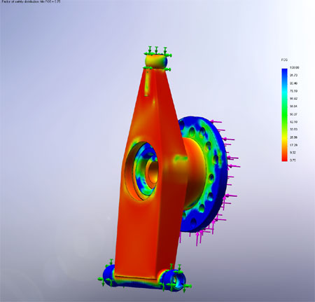
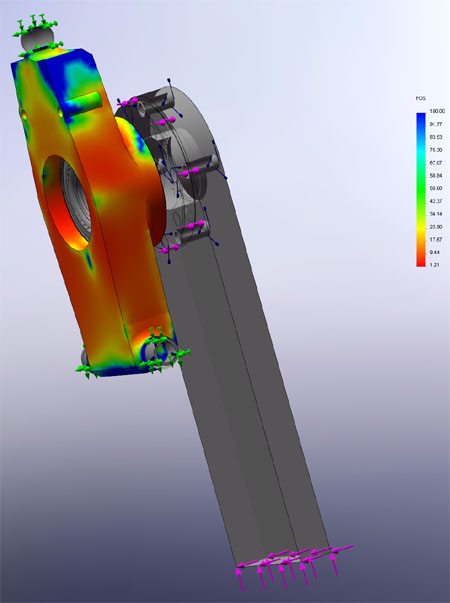
01/19/09 Now that I have a general idea of how I'm going to solve the 3D puzzle that would enable the same upright to work with both UK and US cars and support Wilwood, Alcon and parking brakes, I did some simulations. First I created a model of the existing US upright and applied a force to the face of the drive flange in 3 directions simultaneously. The rear corner weight on an Atom is around 350lbs and 4g loading is a typical suspension strength target so I rounded it up a bit and ended up with 1,600 lbs in each vertical, longitudinal and lateral directions. The real-world scenario would be hitting a bump or an outside curb while cornering. This is of course an approximation of the actual forces and does not include brake torque but it'll do for my purposes.
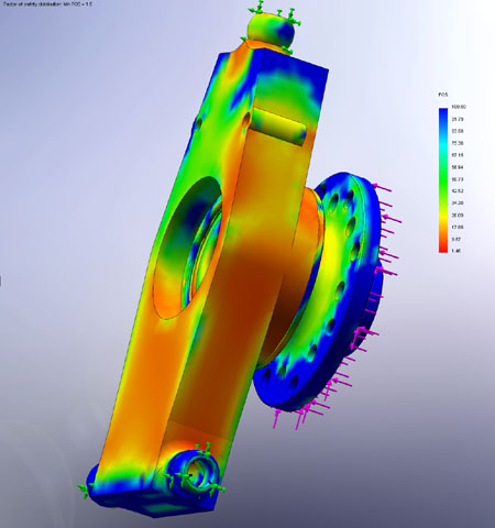
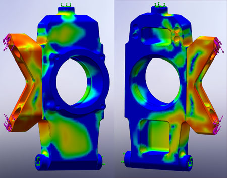
The result, showing factor-of-safety distribuition above, is that the part would permanently deform under this load - factor of safety is 0.75 in the majority of the upright which means it can handle at most 3/4 of this load. This explains why some of these have twisted when hitting curbs. Next I made an initial model of the billet upright that I'm going to make. This is before any optimization or weight reduction.
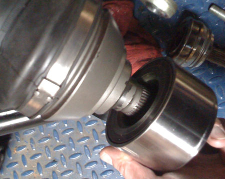
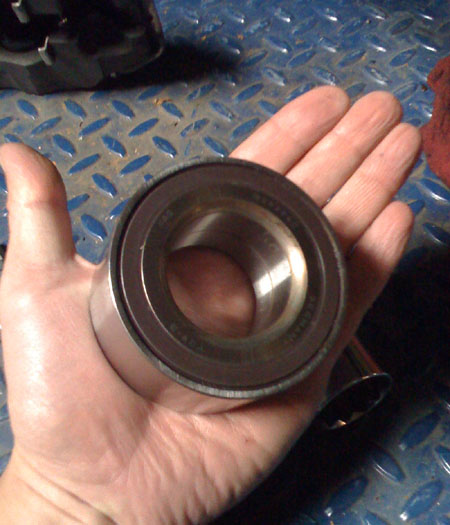
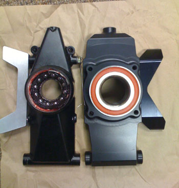
The minimum factor of safety is 1.48 which is basically to aircraft standards and almost exactly twice as strong as stock. Now of course the assembly as shown is 10 lbs in weight vs 8 lbs for the stock one shown above, but like I said this is before any optimization. Still, I expect it will end up about a pound heavier than stock when all is said and done - to me an acceptable price to pay for something that's far less likely to fail. I't interesting to note that the part is fairly uniformly loaded and there isn't a whole lot of material that can be removed. 01/24/09 Got samples of a couple other wheel bearings that might make sense. This particular one is what Porsche uses in the 996 and Boxster and it's fairly large. The overall size is 80mm/42mm/42mm, versus the stock Atom bearings 72mm/36mm/37mm US and 68mm/36mm/37mm UK (as near as I can tell from the remains). The big advantage of using this bearing is that it was designed for installation in aluminum uprights whereas the smaller ones were meant for steel. This means that I can get away safely without using a steel sleeve for the bearing and while the bearing itself is heavier, it is about the same or actually lighter than smaller bearing + sleeve combination. The much larger ID allows for a stronger wheel flange ('hub'), too. All is not without a problem of course since the oddly shaped US CV joint would fall inside the radius and therefore I need to make a spacer with surfaces ground to be parallel after heat treat. A bit of a pain but doable. The UK CV has enough of a diameter to bear on the flat face which is important with the required 300 lb-ft preload on the axle nut. So most likely I'll just go with this bearing. Now I just need to optimize the design and get it made.
As I mentioned previously the simulations I've been running are approximations, to give me an idea of how close to the edge the design is. While evaluating the larger bearing without a sleeve I realized that the cantilever force resulting from the loads being applied at the tire contact patch and not the hub could have a significant effect since the bearing will put considerable pressure on the bore. To be more realistic I created a 'wheel' equivalent to which the upward and lateral force (still 1,600 lbs each) are applied. The longitudinal 1,600 lbs is still applied at the hub because I didn't want to have to deal with torque. Yes, I know, brake torque is very much a part of the equation but this still gives a useful result and in being a somewhat extreme case for a 1,500 lb car it should do for now. The resultant minimum Factor Of Safety is 1.21 - a bit lower than before but still acceptable. With this setup, if someone wants to run 18" wheels with slicks, they can.
02/06/09 The upright design is pretty much complete and parts are being made as this is written. According to the computer it should all work pretty damned well :) I am very confident that the resultant design is better than stock and I'll feel better having it on my car rather than what it came with, especially in light of everything I've learned in the course of this project.
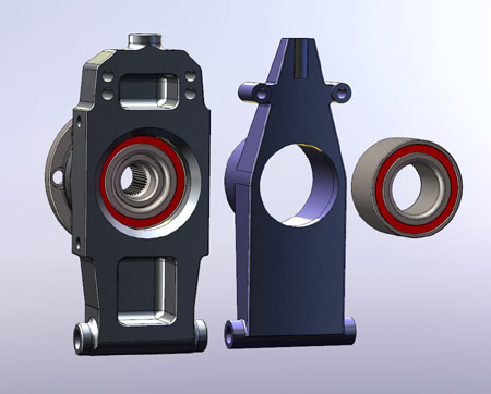
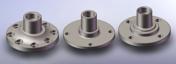
While the new design is considerably beefier than stock (just the bearing is the same outside diameter as the entire stock upright), due to the optimisation I've been able to perform the weight difference is on the order of one pound or less. Below is a comparison of drive flanges (hubs) - left to right is mine, US and UK versions.
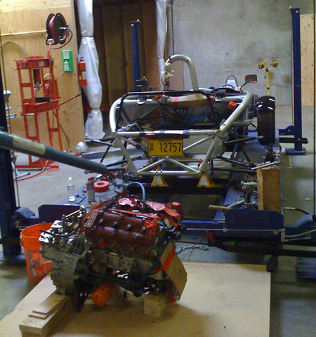
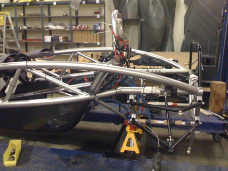
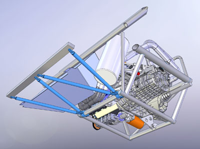
When everything is ready the uprights will be available for sale to upgrade both US and UK versions of the Atom. The price is $1,750 for a complete set of rear uprights including drive flanges, uprights themselves, caliper brackets, bearings and all the necessary hardware. More details will be available soon - email me if interested. I'll work on the fronts next. I've been asked why am I distracting myself with Atom parts when there's so much work to be done on my own cars? Well, both dp2 and dp3 designs will benefit very directly from this project :) The other designs already have. There is indeed a method to my madness, though it may not always appear to be the case. 03/05/09 The uprights are close to being done but in the meantime there's much more that needs attention on this device. I've reluctantly come to terms with the fact that I'll need a much bigger oil tank and the only way to make room for it without creating an abomination is to redo the gas tank (actually there IS another way, a mechanical air/oil separator, and it will be standard on the dp1 but it's impractical to retrofit here). So might as well get it done, especially since the stock gas tank is wide with no baffling and therefore only about 1/2 of its capacity is useful on the track (sloshing causes starvation below that). Also I should really replace the fuel pump that I messed up early on and this too can only be done with the tank out due to extra room taken up by exhaust and the tank being forward from stock position. I'll have a proper fuel cell made once I figure out the exact dimensions I want. An unbaffled, unlined aluminum tank really doesn't belong in a car like this anyway. Of course to get the fuel tank out the engine has to be removed. Making this a good time to take care of a few other loose ends. So, for the first time since its birth, Bikini is temporarily engine-less.
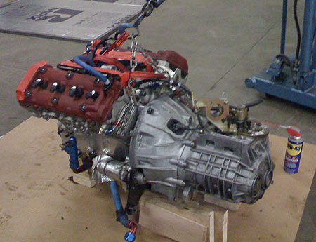
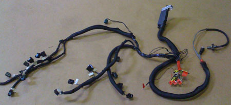
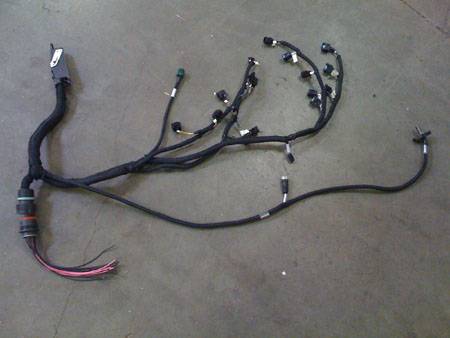
Funny how the gearbox seems to be bigger than the V8. Lengthwise it is. One of the items needing attention is fabrication of a proper wiring harness for the engine. The one in there right now was hand-built and while functional, it's not something I'll want in the customer dp1 cars. So I pulled the harness out and took it over to a local company specializing in making such things. We'll see what the quote comes back as.
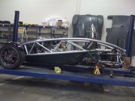
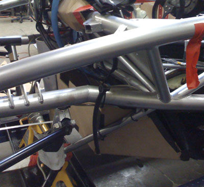
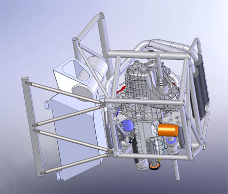
Another item that is one of my long-standing peeves about the Atom is made very clear when the gas tank is out - the lack of structure and triangulation to tie the back end to the rest of the car. When the fuel tank is in, visually it creates continuity and makes one assume the chassis is reasonably braced. Not so.
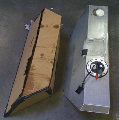
Some may recall I wanted to add extra tubing when Bikini was being built but Simon, the car's designer, did not allow Brammo to do that for me. Would have been much better if it were properly welded and powdercoated with the rest of the frame. As it is, I'll have to make a bolt-on chassis brace, which will also support the new fuel cell and oil tank. On the plus side it'll be retrofittable to existing Brammo cars (the UK ones don't have the Brammo-added tubes under the seats, it's just a thin fiberglass hammock, and the new TMI supplied cars have reverted to that as well). Stay tuned. 03/07/09 Did a quick design of a gastank and prototyped it out of cardboard.
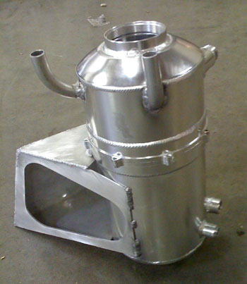
It's actually the exact same volume as the original but sits lower in the chassis and is wider at the bottom instead of at the top, which will lower the CG a bit further. Since it will be a real fuel cell with baffling and internal checkvalves I should be able to use pretty much the entire capacity on the track - with the stock tank I was getting starvation in turns with about 4 gallons still in there. The different shape allows the tank to sit off to the right and makes room for a 7.25" diameter oil tank. John Hartley has already tested this particular oil tank design with the V8 on his dyno and did not encounter any issues. It has double the capacity of the old one and a good internal baffle design. It will also be able to sit much closer to vertical now. The tank is prototyped by a 7" diameter tube in the pictures below. I've already ordered one and it's on its way.
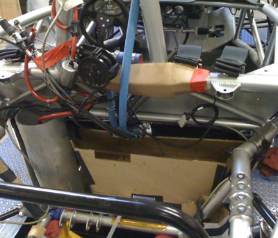
Now I'm working out the deails of the chassis brace. It will cross under the gastank and even though the tank will be mounted to the 'tub', the brace will act as an additional safety measure.
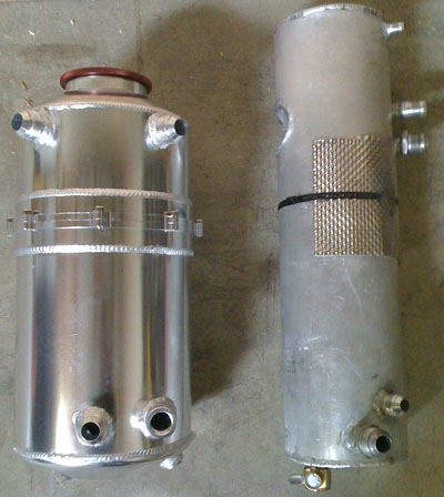
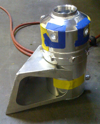
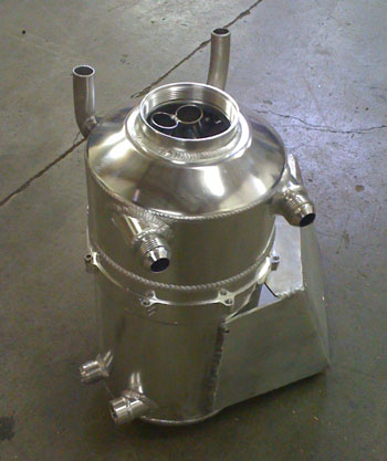
The brace will be a bolt-on setup with minimal modification to the car and should be retrofittable to all Brammo Atoms (but not Atom 1 or Atom 3 because on those cars there's no actual structure inside the fiberglass tub to bolt to). 03/11/09 The fuel cell is designed and has been ordered. Hopefully it won't take too long to get it done. The oil tank has already shown up. Looks pretty good and the baffling inside is quite elaborate and seems to make sense. There are two -12 vent lines which is much better than the single -6 line I had before. The new tank is not as tall as the old one but is still twice the volume.
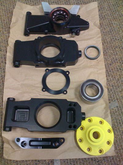
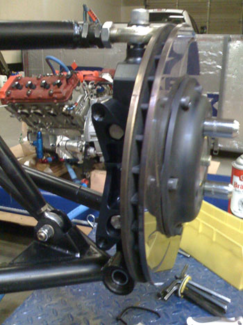
Of course now I have to figure out a mounting method and fabricate the necessary brackets and plumbing but it should be manageable. No rest for the wicked. Most companies have entire teams working on this kind of stuff ;) A quick story on that subject - I once interviewed an experienced automotive engineer who had worked for a Tier 1 supplier. I asked what project he did by himself that he was most proud of. He said a redesign of a seat bracket. He went into detail about how the bracket had to meet certain crash performance criteria and deform in a certain way under certain loads. It was pretty neat actually. I asked how long the project took Two years, he replied. 03/13/09 More parts have come in - most of the upright stuff. Still waiting for the drive flanges and hardware. I need to finalize some of the many varieties of brackets necessary to fit all the permutations of Atoms out there. For that I had the flanges rapid prototyped (the yellow disk in the picture).
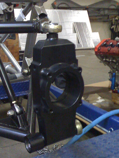
Things are moving forward. I'm signed up for a trackday exactly one month from today. The goal is to have Bikini back together and track-ready by then. This of course depends on several vendors and also me getting a lot of work done so it's going to be close. 03/14/09 Time to test-fit the pieces, measure things for additional brackets and get Bikini put back together. The first shot shows the difference between my upright and the stock one (the bearing is not in yet in this shot).
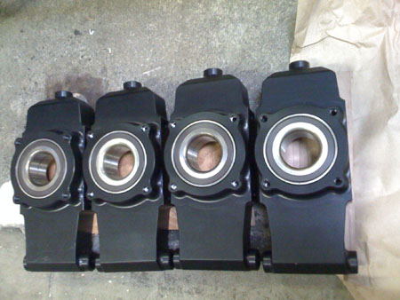
I then went and pressed bearings into a few of the uprights. So far so good.
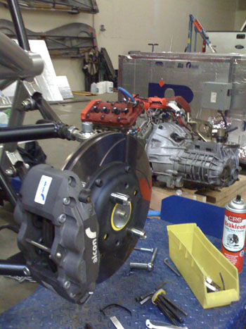
Time to measure the brackets and make sure everything fits, both for the US and UK versions. Due to all the permutations of various brake options getting everything finalized will take a bit. But thanks to rapid prototyping I can do the brackets while waiting for the hubs to arrive. Pictures below show the US, Alcon 4-piston setup (the one I have).
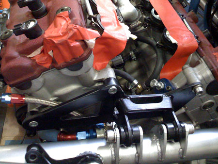
I'll need to put the engine back in to double-check driveshaft lengths and make sure everything is happy there. While I'm doing this, I should really replace all the rodends in the suspension - the stock stuff is the cheapo junk with injected plastic races, never meant for handling shock loads. The pushrod units were replaced a while back, as some may recall, but that was critical because they are undersized to begin with. The generous size of the rest of the parts (go figure) will allow them to live for a while longer but might as well do it right, right? After I'm done with the rear uprights (and the fuel cell, and chassis brace and wiring harness) I'll deal with front uprights and then bellcranks and pushrods. With all this re-engineering and fabrication to do, one might ask why not just build a whole new car from scratch... Well, that's where dp2 and dp3 come in :) In the meantime Bikini makes a nice testbed for all the technologies and solutions, just as intended. 03/26/09 Frustratingly there are delays in getting the drive flanges done but everything else on the uprights is just about ready. Still shooting to get it all back together by the 16th or better yet by the 13th. Karl (our investor) is coming to visit, it will be cool if he gets to play with at least some of the toys. And, OK, I'm anxious to get all the wheels on the track :) To that end the engine is now back in Bikini's frame (the new fuel cell will mount from below and unlike the original won't require engine removal). Taking care of a few minor details we modified the engine mount to clear the shock better. No more ground-off bolts.
We are also cleaning up a few other minor issues along the way. It will be a much better car when done. 04/07/09 Lots of things happening. The fuel cell should ship tomorrow or the day after. I finally have an ETA on the UK drive flanges, and the US ones are close behind. The harness is back from the vendor, they're working on a quote for production dp1 harnesses.
This one is going back into Bikini however. Along with the aforementioned fuel cell and the oil tank. A few other things too.
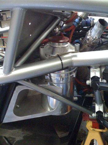
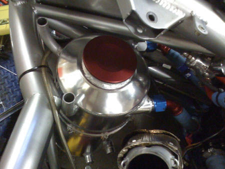
The oil tank of course had to be modified and a mount added to it. I designed all of that and Tristan made it happen.
Of course the customary tight clearances are there in every possible direction - couldn't have it any other way :). Keep in mind that the fuel cell will have the same volume as the original, only a different shape. The clock is ticking and a lot is left to be done before Bikini rolls under its own power again. We're getting there though. On the subject of the clock, we're seriously considering moving our trackday, for a lot of reasons. Decision will be made tomorrow.
|