|
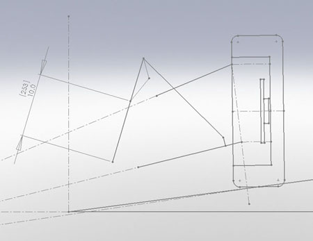
01/07/12 The recent addition of a CNC mill to our shop has greatly improved our ability to do custom work, so I thought I'd illustrate what is involved in a typical project. In this case it's a set of bellcranks. The design process starts with fundamental geometry analysis based on dimensions and other info supplied by the customer.
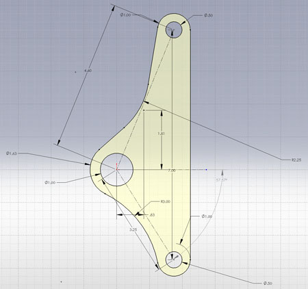
The goal is to make sure that throughout the full desired suspension travel the bellcranks don't overcenter and that the linkage is either linear or progressive, depending on design goals. One common mistake on roadgoing cars is to undersize the bellcrank, resulting in way too much angularity for street-oriented wheel travel and leading to binding up, overcentering and other issues. Also, on a streetable car the bellcranks should be oriented in a vertical plane to avoid large off-axis forces due to the changing angle of the pushrod (race cars have a lot more options because suspension travel is a lot smaller). A regressive linkage is a bad thing that can lead to excessive roll, unpredictable behavior with weight transfer and outright suspension failure. Linear linkage is the most predictable and easiest to tune. It is recommended if antiroll ('sway') bars are planned for tuning the roll stiffness balance at either or both ends. Progressive linkage requires a fairly indepth understanding of the car's dynamics but when done right it can have many benefits. It acts essentially like an antiroll bar by increasing stiffness under load and decreasing it in unloaded conditions. It does so not only in roll but also in pitch, potentially allowing elimination not only of a/r bars but also antidive/antisquat geometry and therefore allowing the shocks/springs to better do their job. Unlike when using an a/r bar, damping remains matched to spring rate and roll stiffness at each end is proportionally increased/decreased with weight transfer. The downside is that it can be a pretty complicated system to design and to tune so it's not automatically the best choice. In this particular case I designed a linear linkage with 1:1 motion ratio for simple, predictable behavior. The next step is the design of the bellcrank itself based on the geometry.
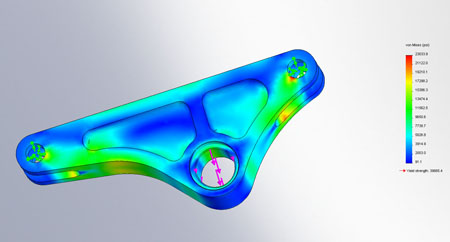
A quick FEA check confirms stresses are in the ballpark (I usually use 4g load case). To get fully accurate results that can be used for things like weight optimisation is a lot of work so for 'reality check' simulations I use constraints that result in higher loads than the part would actually see. If everything has good margins in this overloaded simulation I typically call it good. If excessive stresses are found then either a more accurate simulation or a more conservative design (or both) is needed. In this case the overloaded safety factor was over 1.5.
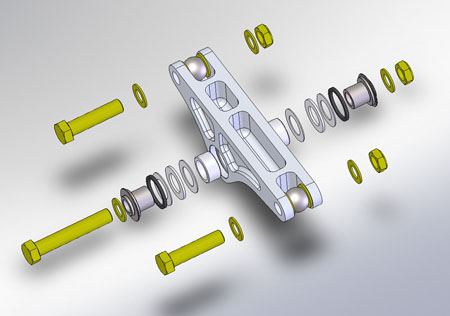
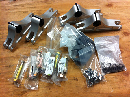
After the basic design is done the details like bearings and hardware are added in and checked for fit/clearances. If a full CAD model of the car were available this would be the point at which the assembly is plugged into the overall design and checked again.
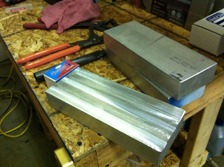
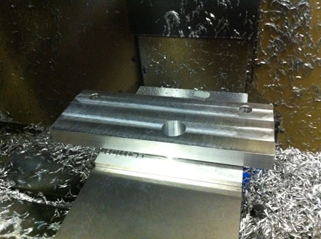
Now the parts are ready to machine. Even having 3D CAD this isn't as straightforward a process as one might think. There are lots of different ways to accomplish the task which actually makes it harder - how do you choose the 'best'? The exact machining steps chosen affect many things. Even the size of raw material can change depending on what the plan is. Once the plan is set and the machining operations are defined, the specific tools and fixtures are chosen and a program is created for each step. There is a lot of art to this and I was fortunate to get some training from an experienced machinist to get me started. The process can be frustrating at first but gets to be quite fun after getting some experience - thinking in 3D and visualizing objects in multiple coordinate systems is something I do well and actually enjoy. In this case I ended up with four separate operations. First, a clean flat face is machined on the raw aluminum blocks. This will be used as a precise reference for subsequent steps.
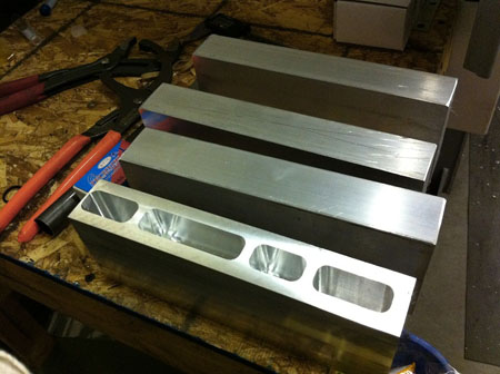
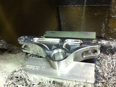
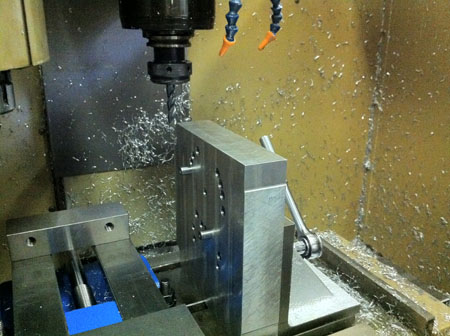
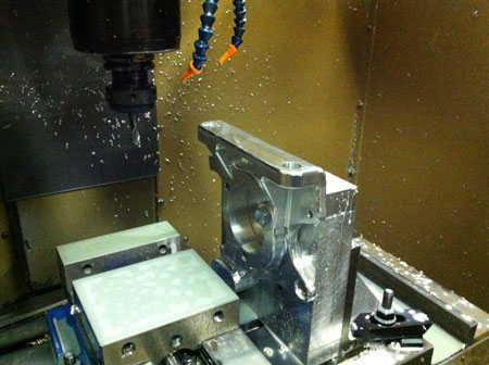
Next, the part is stood up on end and the 'pockets' and clevis openings are machined. In order to precisely align these features with everything else, a reference edge is also machined that will be used in the next setup. You can see it on the left where some extra material was taken off.
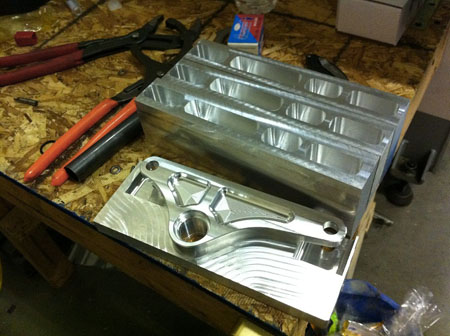
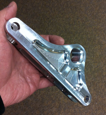
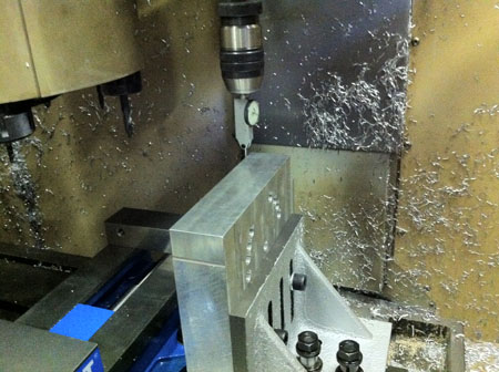
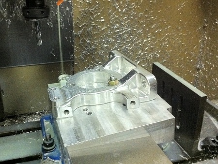
Once all the parts are done in op2, the next step is machining the first side. This can still be done in a vise using the reference edge for alignment.
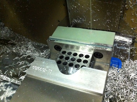
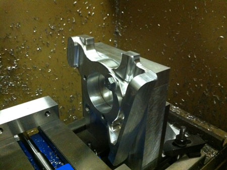
Now comes the tricky part. Since we no longer have two parallel straight faces to clamp in a vise, a fixture has to be made to properly hold and locate the part. In this case I made a 'soft jaw', basically a piece of aluminum that is bolted to the vise with a pocket machined into it to match the contour of the part. Notice that the tool's part number is machined into it in case we ever need to use it again.
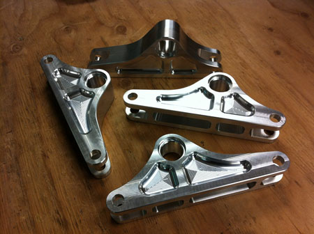
Now the final operation can be performed...
The resulting parts are then deburred, anodized, assembled with all the bearings and hardware, and then shipped off to the customer.
While all this requires quite a bit of effort, having all the resources (and experience!) inhouse allows us to be quite efficient and therefore cost-effective at doing this kind of work. In reality this design is drawing on all the testing and experimentation I've done to date which is quite a bit. By using known and tested parts such as bearings, inserts and hardware we plan on making semi-custom projects like this one an ongoing part of the busines. These can range from individual parts to complete vehicles designed from the ground up and fully documented for production, or anything in-between. Contact me by email if I can be of help. 01/27/12 Here is a bit more about CNC machining. My current project is a set of upgraded Elise uprights. Since the original Lotus design dictates the dimensions for the replacement, it is a bit of a challenge with many features machined at different angles. When you're designing for volume production the difference in tooling cost is ammortized over thousands of parts and is essentially negligible. So designers don't feel constrained by manufacturability as such, they can choose whatever features and angles they like with impunity. When it comes to low-volume specialty market replacements, it gets interesting. For example the rear upright is 8.5" x 9" x 2" overall and there are brake mounting points, upper balljoint attachment point (at an odd angle in two axes) and two lower balljoint attachment points. On a machine with a 16 x 12 x 10 working envelope it sounds doable but the reality offers a few challenges. The biggest is that the cutting tools are 2-3 inches long and tool holders add a couple inches as well. All of which subtracts from available vertical clearance. Also, the parts have to be machined from several sides and the cuts made in each orientation need to be aligned very precisely (the goal is to within 0.001") with all the others. It took me a while to figure out the tricks necessary to make the machine use all of the available space. It involves doing 'dummy' operations out in thin air to prevent tools from crashing into the parts and generally paying very close attention to what is installed when. For example a drill chuck is extra long and if it's in the tool changer while even a 2" tall part is in the vise, it is possible to have the part run into it during a tool change completely unrelated to drilling. Besides keeping tools from occupying same space as the part there is also the challenge of securely holding the part and precisely locating it for machining. For these uprights I designed a vertical fixture that uses precision dowel pins to orient the parts. There are ten different setups that are done in the same fixture - yes, it took a while to figure that one out! A critical part of fixture design is deciding how it is going to be set up with accuracy. This means having a plan for how everything will go together and incorporating features to facilitate it, be it edges, holes or surfaces.
After the fixture is designed and machined, it has to be aligned. A special tool allows setting it to within 0.0005" - naturally it takes a while because even tightening the bolts moves everything slightly. This is also the reason for leaving the vise in the machine while doing the vertical ops - it took a good deal of effort to get it aligned and if at all possible we want to avoid repeating the work.
You can see the tool changer on the left in the picture above. If the part is allowed to move far enough to the left it can get ugly. There's also the fact that the machine goes through its full range of motion on power-up to reset the servos. So even if everything was done carefully but the part was left in the machine overnight, the next day could potentially start with a very unpleasant surprise! Yes, a healthy dose of paranoia is a good thing. After everything is aligned the cutting programs have to be developed for every setup and verified step by step for each part, in each orientation.
It is easy to leave out a 'dummy' op or reference wrong geometry on a complex part. Each single push of the 'GO' button carries potentially disasterous consequences and the various software tools involved don't always do what you expect them to. When I first set up the tapping operation to cut threads in some of the holes, the G-codes generated didn't look right. So I took the safe approach and test-cut a piece of soft plastic first. Glad I did! The first try tore a big chunk out of the material. If it were in aluminum both the part and the tap would have been ruined and maybe worse. It turns out there were several issues with the 'post processor' code given to us with the machine. The POST controls how the general cutting operations are converted into specific codes that a particular machine can execute. It's similar to a computer device driver for something like a printer, which takes general print operations from a program like Word and converts them into commands a particular printer can understand. In our case, the POST was generating commands that confused the hell out of the machine and made it do unreasonable things. Took the better part of a day to fix but now we can tap threads. Another time mysteriously only some of the commands got downloaded to the machine, skipping the critical clearancing steps. Fortunately disaster was averted but only by sheer luck. I went back to confirm and yes it's a bug (one of many) in the software, it just does that. Sometimes. The fix seems to be closing the file, opening another, then reopening the original and then it works. And so it goes... |