|
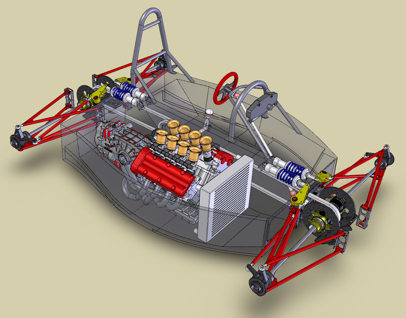
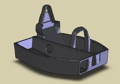
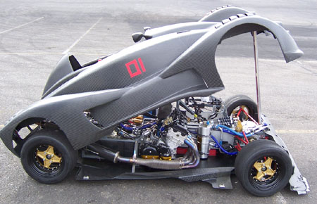
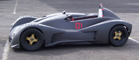
1/21/07 OK, enough philosophy and talk about other people's ways of doing things and back to business. The major focus of the effort right now is chassis design. Quite a few people have written with questions and comments so it may be worthwhile to provide some detail (click for larger pic).
The basic chassis itself is very compact - only 65" long bulkhead-to-bulkhead, 54" wide at the widest point and 12" tall around the perimeter (the backbone is 16" tall). Despite somewhat complicated appearance the main structure has just two pieces - the 'bathtub' and the 'backbone' which are bonded together. The central backbone is the primary load-bearing structure that connects the suspension at the two ends. The aluminum substructures that carry the suspension will bolt up to aluminum plates that are bonded to the front and rear bulkheads. The backbone is triangular in cross-section (with the floor of the bathtub forming the bottom wall) so it will have very high torsional stiffness. Just make a triangular tube out of cardboard if you want an illustration. The chain drive runs inside the backbone. The rest of the bathtub is just there to contain the driver and the motor and to provide crash protection. The floor has some aero features also. Notice that the suspension loads feed directly into the bulkheads so the bolt-on substructures will not affect the overall torsional stiffness in any appreciable way (I know, a couple caveats there) and can be made relatively light. The tubular rollover structures shown above will be replaced with carbon ones, which will integrate additional bulkheads and will bond to the main chassis. the outer skins on those will be 3mm (which is thicker than the required walls for steel tubes) and the interior of the structures will be filled with expanding foam. Lotus was successful in using foam-filled fiberglass for rollover protection in the Elite and some other designs, so a much lighter car with much thicker carbon should work even better. The reason for going with carbon rollbars is more control over shape and the ability to bond to the chassis, spreading loads over a wide area without heavy hardpoints. Many have asked how I'm designing the layup and whether I'm doing any FEA on the chassis. The answer is simple - I'm just following FIA safety quidelines which call for a sandwich of 1.5mm carbon skins and at least 10mm core. Given the compact dimensions and the shape of the chassis, anything designed to that spec will be more than stiff and strong enough and will be essentially over-designed for the loads it would see. Which is just fine. The weight will still be considerably lower than an equivalent steel structure, primarily because of the shapes involved. It is true that in a traditional formula car layout such as DSR or FSAE it is possible to design a steel tube structure that would rival its carbon equivalent for weight and strength but with the dp1 layout this is not the case. For a reality check compare the dp1 tub to the Westie chassis which is considerably longer, narrower, and uses a single (and essentially non-structural due to softness of material) 1mm aluminum skin pop-riveted to a framework of 1" square mild steel tubing.
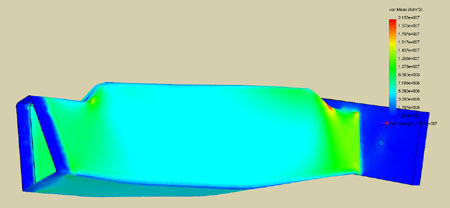
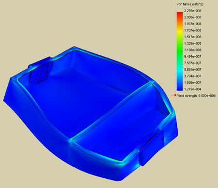
Now granted the Westie is not the pinnacle of either stiffness or safety, but it works reasonably well and serves as a minimum acceptable baseline comparison. The dp1 will be significantly better. In terms of materials I'm quite interested in the SPRINT system from ST. On paper it seems to have many advantages, the primary one being a very low void ratio even with simple vacuum bagging cure. The tensile and compressive strengths they list for the composite with this process is better than heat-treated chromoly steel. As best as I can tell this is due to the dry fabric/hot melt resin setup which allows for more complete air evacuation and better control of resin content than conventional prepreg. They also have a compatible core material although it would be a bit heavier than using aluminum honecomb that seems to be the norm in chassis layups. I would be interested in hearing from anyone with direct experience with SPRINT or similar materials. 1/27/07 The chassis design is progressing nicely so I decided to do a quick FEA reality check. The Cosmos Xpress that's included in SolidWorks is a handy little tool but it does have a number of limitations so I had to create a model specifically for analysis. I just took the backbone tube itself as the minimum, and made it out of 0.187" thick homogenous material (no core). I then constrained one end and created a hefty plate on the other end with two holes 12" apart to which I applied two opposing 1,000 lb loads. There is no torque capability in Xpress but this approach simulates it reasonably well.
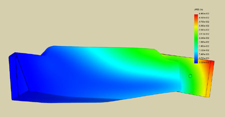
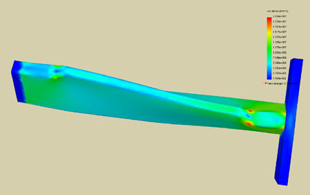
The pictures above show the basic model and the displacement distribution in it (the twist is magnified X180, the actual distortion is just 1/4 degree). This basically tells me that even at this minimum case, just the backbone itself with no core has about 4,000 lb-ft/degree stiffness. The safety factor is about 35 meaning that the backbone structure should be able to take some 35,000 lb-ft torque before failing. At the failure point it would be twisted approximately 9 degrees. The stress distribution below shows a definite 'weak' spot so I'll put a couple extra plies in that area just in case. It's also interesting to note that the elasticity modulus listed for the SPRINT composite is slightly less than that of 6061 aluminum (no doubt due to woven fibers and resin matrix), so the chassis would be about 10% stiffer if made of aluminum of the same thickness. It would also be less than half as strong and about 45% heavier.
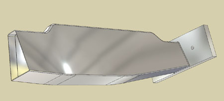
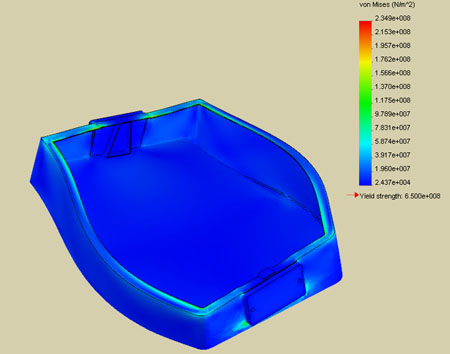
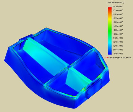
Of course the sandwich core in the layup of the backbone will contribute quite a bit to stiffness, as will of the rest of the chassis - bulkheads and all. So in reality I should be looking at 8,000-10,000 lb-ft/degree, which for a 850 lb car should be plenty. Now all this is of course just rough order-of-magnitude stuff but it does show that the design is reasonable and should work OK even if I totally screw up the fabrication and it only comes out half as strong as it should. 01/28/07 Decided to experiment with the tub itself a bit, too. One reason for doing the structures separately is to see what effect/contribution each has to the whole. Of course the limitations of the program come into play as well (it can only do single parts, not assemblies) and tends to choke on large, thin-walled pieces due to mesh size. I only have 1G RAM in the laptop so it's a limitation of the hardware in some ways, too. Anyway, I first tried the tub as a simple structure with 0.187" walls and the cutouts for radiator ducting. Predictably, it's VERY floppy.
Obviously the cutouts are a very weak point and overall the 'stiffness', if one can call it that, was only about 20 lb-ft/degree. Not much of a 'structure'. Removing the cutouts helps a bit but not as much as one would think. But of course the side walls are not going to be thin 3/16" sheets but 1" thick composite sandwiches which are very stiff. However I don't really have a good way of modeling a composite sandwich that would be accurately processed by Cosmos (if anyone has specific suggestions I'd like to hear them). So instead I decided to experiment with adding a thin (3/16") lip around the perimeter. A 1" wide lip produced a 3X stiffness improvement and further widening it to 2" resulted in a 200 lb-ft/degree stiffness - a full 10X gain over the original (the distortion in the pictures is scaled so it appears the same but the top picture is 0.8X scale and the bottom picture is 8X scale, both with 1000 lb-ft torque applied). Strength went up 3X but of course the whole thing is still nothing to write home about.
FEA is certainly very useful for this kind of stuff. While it's not a very accurate representation of the actual part, this does give a good feel for where the critical areas are and which changes result in real improvements and which don't. For example, putting a 2" radius on the four inside corners of the lip provided a further 10% improvement in both stiffness and strength. Adding a 3/16" thick bulkhead with a 2" cap increased stiffness to 800 lb-ft/degree but without improvement in strength (critical stress path was not helped by the bulkhead).
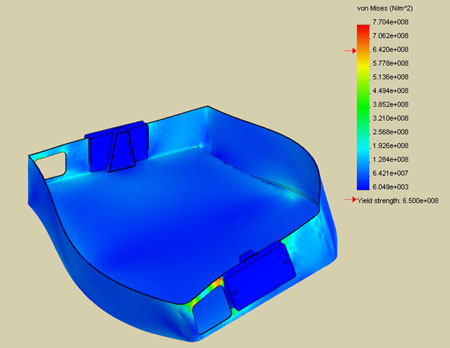
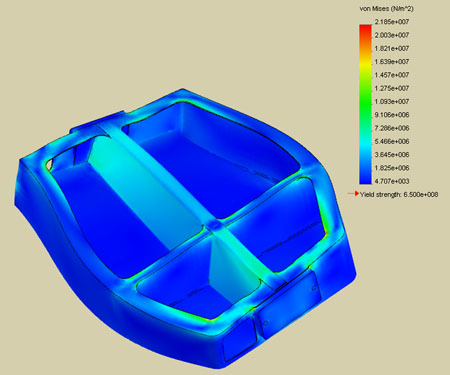
So just adding a 2" lip and a bulkhead has resulted in a 40X stiffness gain for less than 5% weight increase. And finally, adding a simplified version of the backbone is the 'miracle fix' - stiffness further goes up10X to a little over 8,000 lb-ft/degree (a 400X gain over just the original thin tub!) and strength also goes up 10X while weight increases only 16%.
This is a very dramatic illustration of the efficiency of the backbone structure (mostly due to the fact that it's a closed box and a direct load path but the triangular crossection helps too). The picture above clearly shows what carries the stress, so my intuitive assessment was mostly correct - the backbone will be doing all the work, the rest of the chassis mostly wraps the components and driver and provides crash protection. However what is interesting is that the combination of backbone and tub is twice as stiff as backbone alone and much stiffer than a simple sum of the two parts. And as a final experiment I increased the 'lip' to 3" and added a couple radii. Stiffness went up to 11,000 lb-ft/degree even with radiator cutouts. Of course this is not necessarily a practical shape but much can be learned from it. It's quite a step up from the 20 lb-ft/degree I started with at the cost of only about 30% weight increase. For comparison the Elise is supposedly 7,400 lb-ft/degree and that's a car that weighs a bit over twice as much and therefore sees much higher loads.
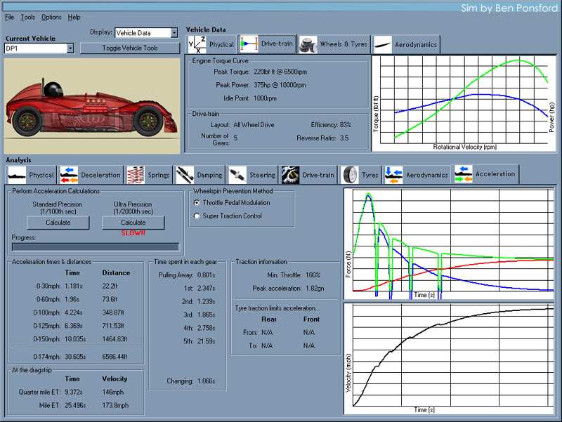
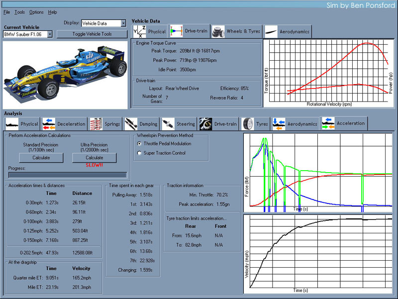
Again, none of these numbers should be taken as absolutes but they are a confirmation that I'm generally in the ballpark and they do show the effects of the various changes. Fun. 02/24/07 There has been a lot of discussion of the dp1 on the LiveForSpeed forum. It seems there is a lot of support in the LFS community for the inclusion of the car in a future version of the sim, so hopefully this can happen at some point. Would be a lot of fun. In the meantime, one of the forum contributors ran an acceleration simulation. The results correlate well with my own calculations, with 0-60 time of about 2.0 sec and 0-100 time of about 4.2 sec (click pic for larger version).
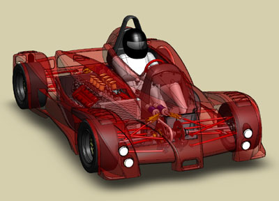
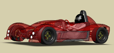
The simulation assumes the power spec for the 2.6L version of the v8 (2.8L that I'm using should be closer to 400hp but I don't want to officially claim this until I do some dyno testing on Bikini). This performance is on par with a modern F1 car and it can be yours for only $125K - that's less than the cost of a used Ferrari :). UPDATE: Speaking of a Formula 1 car, in the sim it looks like this (click for full size):
The comparison is interesting and illustrates the various performance aspects that I talk about on the dp1 site SPEED section - namely power/weight, power/traction and power/drag. You'll see that the F1 is traction limited to about 83mph and so can't use its full power until then. Hence its 0-60 time of 2.34 sec vs 1.96 sec for the dp1. But once the tires hook up, it's gone - the power/weight ratio of just under 2 lb/hp and a better power/drag ratio put it 0.25 sec faster to 100 mph and power the car to over 200 mph vs my top speed of 178 mph. Now granted this is a simulation and cannot be taken as absolute but doing a quick reality check against my own calcs and available data out there it seems quite accurate. A lot of details are taken into account in the sim (from wheel rotational inertia to suspension setup) and it should be a very useful tool for playing with various settings once it's available. The program is still in development as of this writing. 03/28/07 Although it's been a while since last update, work continues. It's just that it's not all that glamorous and consists of a lot of detail tweaking. There is some progress on the carbon rollover structures (will definitely need FEA here) and the chassis overall. The main tub is four major pieces bonded together, then the rest of the stuff gets bonded to that.
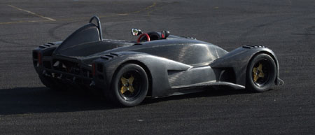
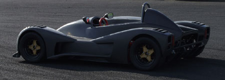
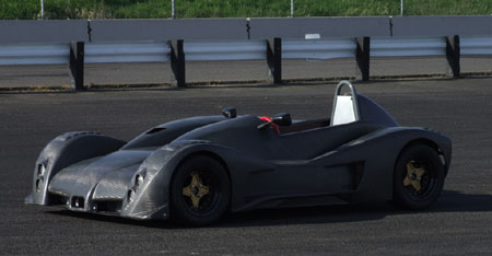
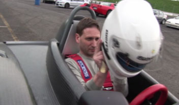
The cockpit side panels still need to be added. Same goes for much of the underbody aero structure. It's all modeled in my head, just not in the computer yet. But that will change shortly. In the meantime, on the prototype I changed alignment (toe out at the front instead of toe-in), set corner weights, fixed brake switch and made a new, much larger catch tank for the center diff. The prototype with bodywork and all fluids is 950 lbs which is considerably heavier than the original target - I definitely have my work cut out for me with the production version. Solidworks says I'm still OK for the 850 lbs weight but much detail remains. We'll see. The car is definitely gathering more attention, with addtional media coverage and increased interest from potential customers... Got to get it done. 04/03/07 Taking a break from the theoretical and going back to the practical, the first dp1 trackday for the season - a MotoCorsa/Lotus Of Portland trackday. I again signed up to instruct so the first half of the day was spent doing that. Just as well - the day started out clear but quite cold, only 34F in the early morning. I tried a few maneuvers in the parkinglot and found the tires to be rock hard and slippery. So I just took a few pictures and parked it until lunch.
Over lunch I was able to get a few laps with the track all to myself, which was a good opportunity to work up to speed slowly and see what's what. The tires were very slippery despite the temps having risen to high 40s. I don't know if it's age (they are four years old now), the heat cycling, or a combination of both plus the low ambient temperature, but the car was moving around a lot. The tail was coming out on turn-in although it was easily reigned in by application of power.
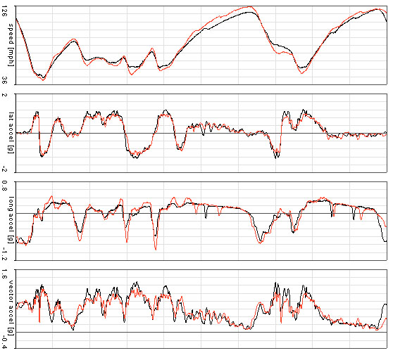
Looking at the data, the lap times were somewhat disappointing, a best of a touch over 1:30 which is slower than the last outing. I would have hoped to improve rather than regress. The plot above (red trace is today, black trace is from last fall) tells the tale - I'm actually accelerating more and picked up a good deal of speed on the straights but the corner speeds and g loads are way down. I could not for the life of me to get any heat into the tires, despite dropping pressures to 12.5 psi. They were cold to the touch coming off the track and the data confirmed it - only 1.1g lateral and the car was actually sliding. These same tires generated 1.75g at the kart track but that's when I was able to get them warm. I guess the constant cornering of the kart track was better at warming them up. The day was warmer too, and the tires hadn't heatcycled yet. I'm sure there are several factors at work here but I'm left wondering what to do about it. Chances are, replacing tires is the thing to do. I'm actually contemplating getting a set of slicks... Even with the tires as they are, though, it was obvious that I was not using the car anywhere near its capability. This is a combination of being understandably hesitant to push hard this early on in the testing and the fact that I still have a ways to go as a driver. I know what a 1:30-ish lap looks like and can drive it pretty comfortably, but pushing much faster than that requires recalibration of entry speed and braking points which I have not yet done. All in good time - better too slow than too fast, at this point in the game :) For the most part the day went smoothly although a number of maintenance issues surfaced. I had misguidedly added oil to the drysump tank with the result that some oil was spilling out. At least I now know what the proper level is. The rear chain sprocket is rubbing on the stainless cover so I need to see why that is and likely replace the rear chain, too.
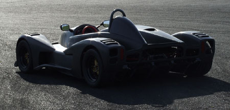
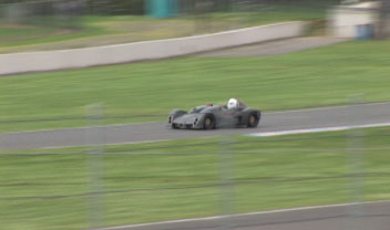
On the plus side, the alignment change seems to have worked well and the car feels very good on the straights. There is some sensitivity to cross-wind which will be the subject of further testing and aero experimentation. Overall, it's working quite well for a first effort. But definitely a lot of things need to change for production and a lot of lessons are being learned. This is what it's all about. 04/10/07 (updated 4/11) My friend Roy had taken some video during the last trackday. Unfortunately there's no sound but the video turned out pretty cool... (21M file)
UPDATE: Since the original video was recorded in HD I decided to try and render it out in higher resolution. The size penalty wasn't all that bad so the updated video is now at the link above. I've been putting off the maintenance on the car (a lot of work projects going on and I'll need to remove the floor, for which I should really move the lift to the shop although it's perfectly doable as-is). One thing I did do is decide to replace the tires. Eventually I'll want to try real slicks on it but for the moment I wanted to see how the current Hoosier A6 would work so I ordered a set of those. Should be showing up in a few days at which point I'll need to remove the wheels so that'll give me the incentive to get the other things done as well. Next track outing for the car is likely to be May 8. 12/01/07 This is an interesting stage in the project's life. The steps required to turn the prototype into a manufacturable, fully functional vehicle are quite capital intensive. Having personally funded all the development up until now, I have decided that it is the appropriate time to bring in outside resources. Of course what I'm learning is that business deals, especially those involving things that don't quite yet exist as such, are at least as difficult and time-consuming as the development process itself. No huge surprise really, and not a complaint, but it is quite educational to look back on what it took to get even to this point (no, I'm not going to share any of that - that is hard-earned experience which I'm keeping to myself! :). And no, nothing is final yet, but if all goes well the dp1 will start moving forward rapidly and will spawn several intriguing offspring as well. There are definitely some very exciting things afoot. But, alas, that's about all I am going to say at the moment. While the business stuff takes its course, there have been several other dp1-related efforts underway. One of them has to do with simulation of vehicle behavior. I mentioned this particular simulator earlier - written by Ben Ponsford it is quite a handy tool to gain insight into what makes a vehicle do what it does, and what effect the myriad of assorted settings might have on its behavior. The sim is now publicly available and can be downloaded from www.vehicle-analyser.com. (updated 1/9/08). There is a setup file that is now part of the package which needs to be loaded because the default settings in the executable file are not correct at the moment, at least as of V3.1.0. Once VHPA is running, go to File->Open, navigate to VHPA folder and pull in dp1_reference.set file. It is very educational to tinker with. Of course there are more fun pieces to the puzzle that will be made public in a bit, so keep checking the site for updates. I can definitely say that I have learned a tremendous amount in the last few months and this trend is going to continue. Fun stuff :) So while it may look like there's no dp1 activity, worry not - that isn't the case! |