|
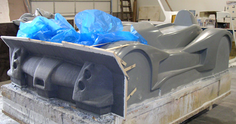
09/23/04 Stopped by Composites Unlimited to see how the tooling is progressing. Well, at least the nose mold is now done - 16 layers of glass and epoxy resin, pretty heavy-duty stuff. When I asked how it is going the response was 'slow' which I guess is a polite way of saying 'expensive'... Looks cool though.
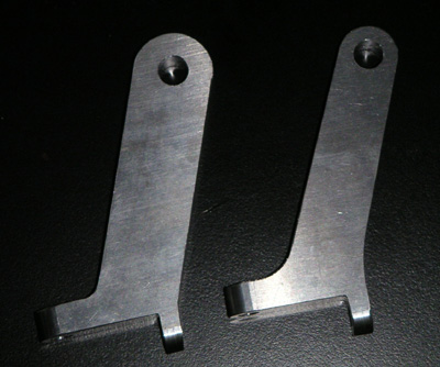
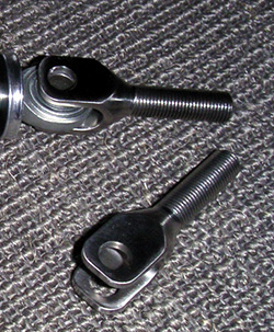
It was nice to see the car's shape again - it's been a while, and seeing it somewhat 'in the flesh' has definitely lifted my spirits and enthusiasm. Also today stopped by a local tube bending vendor to talk about the frame. It has finally sunk in that I'll have to break it down into sub-assemblies that can be easily manufactured and then welded together in a way that does not build up tolerances. Suspension pickups would be welded last to make sure they are in alignment, since that's really the only part that matters anyway. I'm also thinking of skinning the box section with riveted aluminum panels rather than trying to use tube triangulation for stiffness. A couple people have suggested this in the past and it does make sense, especially as I think of how to put the thing together. So, overall there's progress. Some setbacks too, but if it were easy everyone would be doing it, right? :) Just have to deal with it I guess. 09/26/04 Recently I had to have the steering arms remade due to a manufacturing issue. I decided to use this as an opportunity to update the design with what I learned from FEA earlier. The new part is on the right - it's 25% lighter and considerably stronger, too (the tight radii at the base were stress risers and the extra material was wasted elsewhere). Geometry is unchanged.
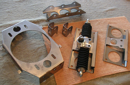
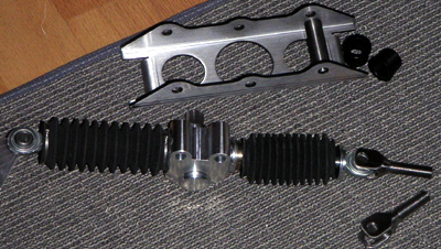
Another challenge turned into a solution as well, since I had decided to upgrade the upper rodends after FEA showed them to be marginal in bending. Originally I was going to have my former vendor redrill and retap the uprights for the bigger parts at $20 apiece, but since he is no longer interested in doing that I looked for another solution and realized I can simply use off-the-shelf sleeves at $1.80 per corner. Not that this amount of money really makes much difference in the grand scheme of things, considering what some other items are costing me, but problem solved and that is satisfying. And yes, I'm back to combining some earlier pages instead of adding new ones (laugh if you must, John - I guess even people trying to innovate can be set in their ways sometimes ;). While going through early entries I realized it's been over two years since I took the Hayabusa apart. Time certainly flies. This project is one hell of a learning experience! It'll even cost about as much as a Masters degree except I'll (hopefully) get a car for 'graduation'... 10/09/04 A bit more progress - some additional chassis brackets showed up. The large piece is what aligns the diff carriers (chain load is carried by another structure via a 1/2" AN bolt). The steering rack bracket is bolted in instead of being welded - this is to allow for use of belts in later versions. When installed the bracket carries the steering rack and serves as a structural bulkhead for the frame backbone. On the advice of several people and after some deliberation I've decided that the backbone will be skinned with riveted aluminum panels in a semi-monocoque arrangement rather than trying to use tubes for triangulation. This should make it lighter, stiffer and leave more room inside for drive components.
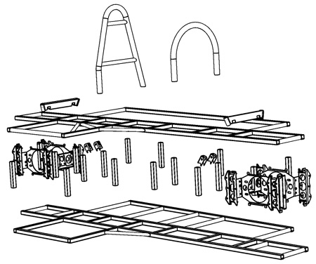
When faced with communicating frame dimensions to vendors I realized that I had to redesign the frame slightly to simplify manufacturing. Combined with the decision to use aluminum panels for stiffness this led to a configuration consisting of two 'flat' pieces made of square 4130 tubing, stacked on top of each other and joined with vertical tubes of equal length and various brackets that I already have. The two main pieces can be fabricated in the same jig as they are nearly identical. The suspension pickup brackets would be welded last to assure that those dimensions are maintained in tolerance even if the frame itself distorts a bit during welding.
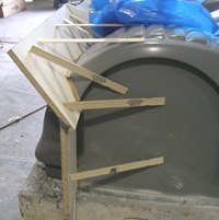
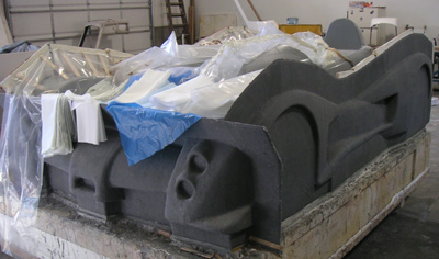
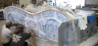
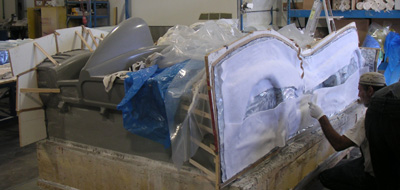
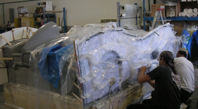
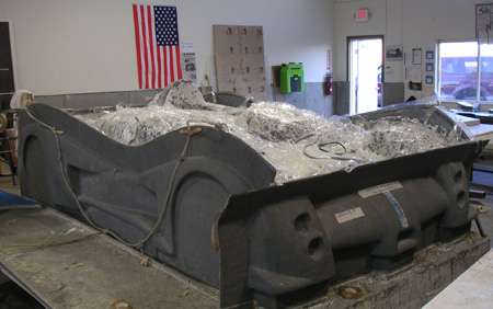
The pictures don't show rollbar bracing and some other minor structures, but basicaly illustrate the new frame concept. Weight is essentially unchanged from the previous version. This should be sufficient for the first prototype, then I can revise it as need be for subsequent cars. Eventually there may be a carbon backbone with a bolt-on rollbar structure to protect the driver. We'll see. In other news, mold construction is moving forward albeit slowly. In addition to the nose the left side is now done. Right side, rear and top still remain. Also, there is some progress on the floor mold although at the moment it's waiting for some materials to arrive. 10/13/04 Drove out to Scappoose to check on the progress of the molds and make another payment. They were just getting ready to vacuum-bag the right side mold so I got the pictures of the completed left side and some of the steps for the right. Pretty cool.
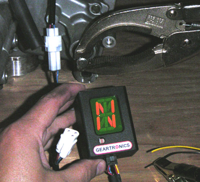
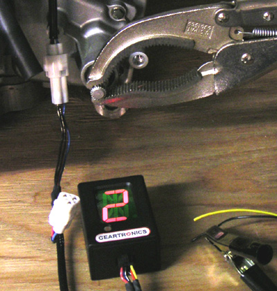
The flanges on the mold give it an interesting look - like a lizard of some kind. It's been quite an effort to get this far and I'm eager to see the first body come out of the molds. That first piece will be mostly for test-and-fit purposes and will consist of 0.040" of prepreg carbon thickened to 0.100" around the edges, no core. That will tell me where the body is flexible and needs reinforcement. Or if I get lucky maybe it'll work as-is in which case it will be quite light (under 40 lbs). We shall see. In other news, I finally got a good quote on the frame from a vendor in California so after I get him the final drawings there will at long last be progress on that front. So things are looking better, for now... 10/28/04 Received the gear indicator from Geartronics. On the 'Busa the top three gears are so close it's not always obvious from RPM which gear you're in. In the Westie I'd ofen find myself trying to grab nonexistent 7th when driving around on the street... On the track when I could get clean laps I'd just figure out how many downshifts I need for each corner, but if there was a slow car in front slowing me down then sometimes I'd get 'out of sync'. The Geartronics unit has a large, bright display and should eliminate the guesswork. Plus it looks cool :) A useful feature is the 'timing retard eliminator' - the Hayabusa ECU runs different ignition maps depending on gear, backing off the throttle response in the lower three to help keep bike riders from flipping over backwards. Gears 5-6 get a modified map to account for ram air at speed. The TRE fools the ECU into thinking it's in high gear all the time so the 'unrestricted' map is used. This mod can be done easily with a resistor (I made one for the Westie but never got around to trying it) but having it built into the indicator saves the hassle. Also the indicator comes with OEM connectors that simply plug into the Suzuki harness which is nice - no wire cutting needed. I hooked it up to a 12V source and connected it to the motor, using vice grips for a shift lever. Works like a charm.
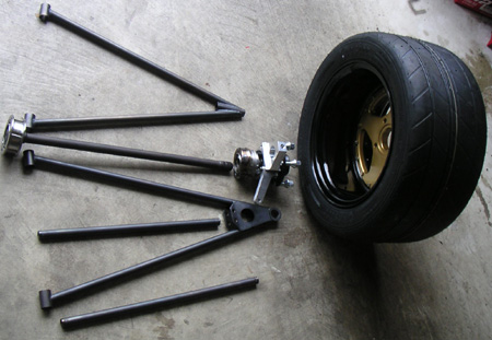
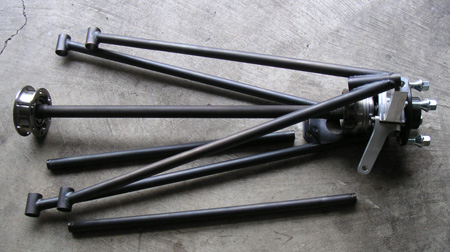
Display is bright enough to not get washed out by the flash so it should work well even in sunlight (there is a photo sensor below the display to automatically adjust brightness). Initially the green tint of the window threw me off but the display itself is bright red. Cool. Now all I need is to get the car done! :) 11/01/04 Some of the suspension parts came in. They are being made by Formula World Racing in Georgia, somewhere around Atlanta I think. FWR actually made all the tooling jigs for 'volume' production, although initially I'm only building 2 cars. The plan is to build quite a few more of course. So far I have the upper wishbones, pushrods, tierods and bushings.
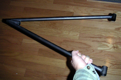
This is where having identical parts at all four corners really pays off. Much easier to make and to keep track of. Lower wishbones are also done and are on the way. The parts look great. It is interesting to see the suspension arms in the flesh - I had of course designed them to be quite long, but it doesn't sink in just HOW long they are until one has them in hand.
Also, the steering rack came with 3/8" rodends but try as I might I could not locate matching clevis ends. So I had to design them and have those made too. Came out very cool - stainless of course.
In other news I've mailed off the brackets, production drawings and a check to the guy who is going to build the frame. So progress is upon me, ready or not. Speaking of production drawings, that's something I really don't enjoy doing and something a guy just building the whole car himself doesn't have to worry about. On the plus side, once I'm done I'll have a fully documented, manufacturable design. To be fair SolidWorks makes the drawings pretty easy. My reluctance to tackle the task is more of a psychological thing than any real difficulty :) Wednesday I'm going to stop by Composites Unlimited to check on the molds. They've hit a bit of a snag with some personnel changes but assured me that work would resume shortly. There are two potential new vendors along the route, too, so I'll stop by and visit one of them. 11/11/04 Dropped by Composites Unlimited to check on status and talk about completion. The bodywork molds are pretty much done - they were in the process of curing the last of 16 plies on the top mold, which is the largest and most complex of the five pieces.
After this a steel frame gets bult to support the molds (but still allow them to come apart). Then the whole thing goes in the oven for low temp post cure since the plug can only take about 150F. Then the molds get popped off the plug, reassembled on the steel frame and cured at high temp (about 300F). When all of that is done they'll lay up the first body, which will be two layers of 12K carbon, no core. It will be a test piece (quite pricey too) to see how light it can be made and whether and where it needs reinforcement. With luck it will all happen this year still. The floor mold and the first actual floor are targeted for the same timeframe. In other news, the construction of the chassis got the green light so just maybe I might have many of the major pieces done before 2005 rolls around. It'll be pretty close, anyway. Current target for having something driveable is March. We'll see. 11/24/04 Suspension lower arms showed up. I now have most of the suspension pieces and need to figure out what kind of protective coating to use on them. Maybe electroless nickel, maybe powdercoat...
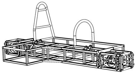
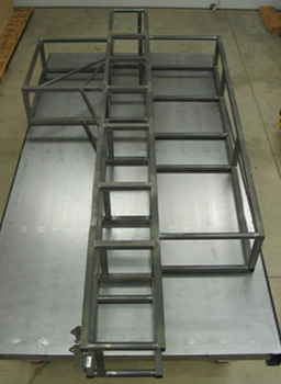
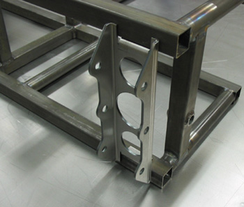
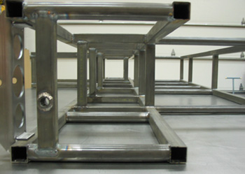
I've got a few weeks to figure it out. Mid-December I'll be down in California to check on the frame progress. On the bodywork front, the steel support structure for the molds is being built. Once that is done the whole thing will go in the oven for post-cure, then the big moment of popping the molds off the plug. The plug itself will go into storage. Wish I had someplace to put it for display as a sculpture of sorts.... Might have to figure that out later. 12/06/04 Got first pictures of the frame in progress. It's being built by Philip Burke in California. Looks cool:
Friday I'll travel down there to see it in the flesh and go over some details and plans. All the sheetmetal brackets should be on by then. Things are moving along.... |