|
07/12/04 Doing more detail work such as locating the shock pickups (and designing the brackets to do the job) and verifying that everything works and clears throughout suspension travel...
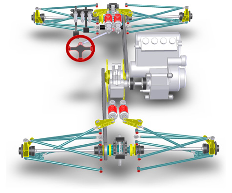
Yes, the steering shaft clears the shock and all the frame rails. Barely. Actually all clearances seem to be 1/4" or better so hopefully that will translate into parts not hitting each other in real life. Suspension travel is 3" total (+/-1.5") which is fairly generous for a car like this. Long wishbones help keep geometry under control. Also someone e-mailed me with a good reason not to use ballbearings in a partial-rotation setting like a bellcrank. The balls don't end up rotating all the way around and wear unevenly and quickly. Needles in a bearing are much smaller in diameter and do make several complete revolutions even as a bearing only rotates a fraction of a turn. Hadn't thought of that - thanks, Gary! So now I need to pick the appropriate needle bearings. On the subject of wishbones, today I got first pictures of the fixtures and parts being made for the suspension. Looks really neat!
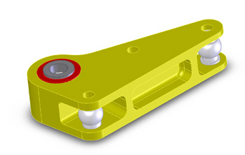
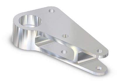
Of course today was also the day I realized that I screwed up the bore tolerance on lower suspension arm bearing carrier and so one fixture will have to be modified. Damn. Just goes to show that CAD cannot make up for human error. It's like my halfshaft fiasco all over again. I wonder how many more such mistakes I've made that have not been discovered yet. We'll see... :) 07/20/04 Been working on the car almost full time. Lots of detail work. As some details get refined others have to change. Then I stare at the whole thing and spin it on the screen for a while and come up with a different (hopefully better) way of doing it, so I redo a few things. And so it goes... Settled on 35mm tapered roller bearings for the bellcranks, talked to Jon about machining the parts and made some more changes based on the recommendations. Hopefully will start on making those soon. This is how the part looks at the moment:
Also changed from using a BMW 2002 'guibo' and a CV joint to two BMW 325i parts. I think these will work a bit better and the parts are lighter, too. Also picked new bushings for the engine mounts and came up with a way to do the mount itself (but have not put it in CAD yet). Ditto for front and rear diff mounts. Getting quotes on laser-cutting the drive flanges for the short propshaft. Still need to finish the design of the adapter that goes onto the input shaft of the reversing box. It has to be long enough to let the bolts that attach the 'guibo' clear the forward chain. Quite a 3D puzzle :)
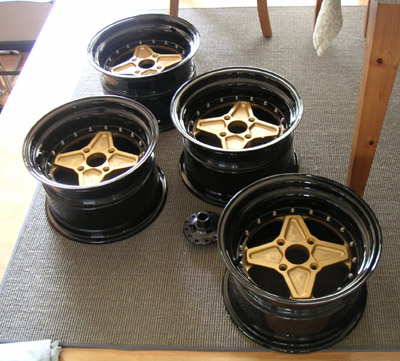
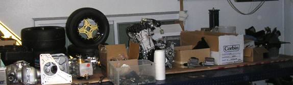
In other news, after several months of waiting the wheels finally came in. Neat. Yeah, I know, they're GOLD... They'll look OK on the car - trust me :)
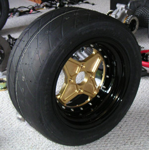
I designed the centers myself but of course nothing goes without some kind of challenge and so somehow communicaiton broke down and they didn't get made to print, so I ended up with offsets that are 3mm less than what I specced. It'll still work, I think. They are also a couple pounds heavier than I had hoped, weighing in at just under 10 lbs apiece. I went and got the tires mounted, and the complete tire and wheel assembly is 25 lbs - two more than anticipated but still pretty decent overall. Using slicks would probably save 3-4 lbs off that. On the plus side, the units balanced nicely and required very little weight.
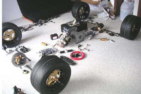
It's still only a pile of parts, but it's getting there. Also, I've pretty much decided to go with a turbo right off the bat. So now I need to procure those parts as well. If only someone would buy the Westie already.... Sigh. 07/21/04 All along I've been having all kinds of compatibility problems between SolidWorks and the ATI graphics card I had in my machine. Lots of limitations and frequent crashes. When I recently went to a SW05 intro (the thing looks SWEET, can't wait! Well worth the maintenance $$$$) I asked what cards they recommend. Turns out NVidia is it so I ordered a card with Quadro 4 and now that it's installed things are much better. One neat feature is RealView, which provides a photo-realistic view of a part once material is specified. Yes, it spins and moves in 3D in real time with all the reflections updating on the fly. Amazing. I have a special appreciation for this knowing exactly what kind of computing power is required to achieve it- 3D graphics was a minor of sorts for me in college. Let's just say it would have cost millions only a decade or so ago. Now it's $374.
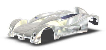
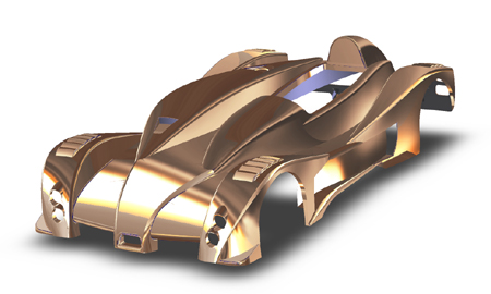
Of course I couldn't resist a diversion and had to find out what the bodywork would look like in aluminum or bronze... Now you know :)
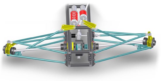
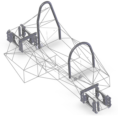
OK, enough silliness and back to work. So much of it remains it's almost scary. I'm now thinking end of the year for driving tests. Of course the weather will be a challenge by then... 07/22/04 Working on the frame. In current version of SolidWorks doing tubular assemblies is quite a bit of a pain. However the new '05 makes it a snap - the problem is I won't have it for at least another 3 weeks. In the meantime I've decided to get the foundation done anyway, so I've made a 3D sketch (the picture below shows it after about a dozen iterations, probably with a few more to go). Tubes will be inserted using the sketch once I get the new software. Maybe I can score a beta version to tide me over...
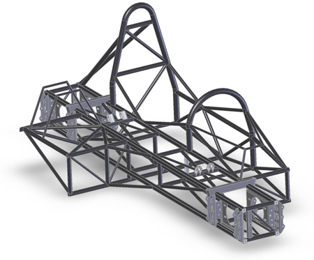
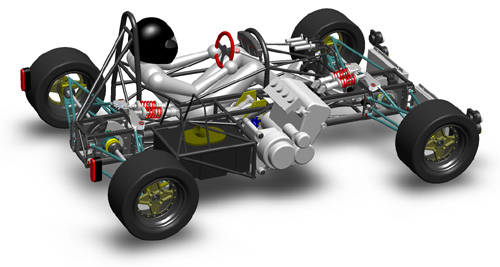
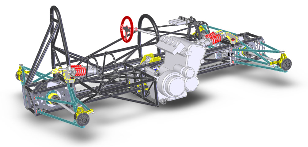
It's a little hard to tell from the pictures where all the tubes go, but basically most of the structural load is carried by the central backbone, now appropriately triangulated. The rollcage adds some to the overall stiffness but is mostly there to protect the driver. The tubular structure enclosing the fuel cell also doubles as most of the engine mount. The engine hangs by four fairly stiff rubber bushings giving unobstructed access to the front and the side for service. The target weight for the frame is 80 lbs and it will be pretty close to that if initial calcs are any indication. Making it will be a challenge ;) 07/23/04 Grabbed a Beta version of SW05 from the SolidWorks website and made the frame. I must say the functionality in '05 is awesome. Converting a sketch into a frame only took a couple of hours, without reference to a manual of any kind... Since I posted the first frame sketches yesterday I got six e-mails about it. Two were questioning the torsional stiffness and four were saying the frame is overkill for a small/light car like this :) I've tweaked the design quite a bit today and will probably do so a few more times as I refine the final details.Yes, there will be aluminum skin riveted to it in some places, mostly to contain the chains and any stiffness that adds is bonus (the frame rails also serve as chain guards). In fact some of the biggest loads in the frame come not from suspension but from chain tension - a peak of over 4,000 lbs on each chain now that I'm going with turbo, resulting in some 5,000 lb-ft of torque on the center diff about the vertical axis. Yes, there are extra bearings and support plates to deal with it and offload the diff housing. That's why the whole center diff assembly weighs over 60 lbs and costs over $8K and why I'm so eager to get rid or it in the next version :) This is what the frame looks like in the meantime:
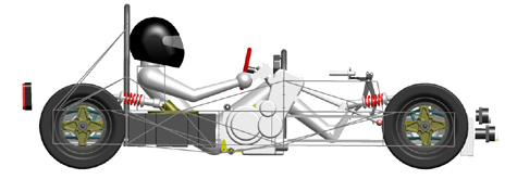
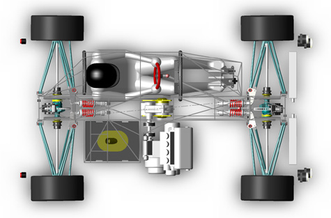
Before I get even more e-mails on the subject, consider that just the backbone is stiffer than a Europa or early Elan chassis, plus there is the rollcage that those car lack (and my car is about 2/3 the weight and over a foot shorter in wheelbase). For those claiming it's too complex, the frame has fewer tubes than the Westie one and weighs roughly half. Almost everyone asked if I'd done FEA on the frame. No, I haven't. But if somebody wants to try it as an exercise let me know - I'll send an IGES or equivalent. It might be educational... 07/24/04 Doing still more work on the frame. To illustrate the efforts I e-mailed someone a picture and got back a comment how nice the rendering program is. Which made me realize that not everyone is aware of just how powerful modern graphics hardware is. The pictures I've been posting are not 'rendered' - they are just screen grabs and then shrunk down for web size. Click on the picture below to see it at screen resolution, that's exactly how I see it when I spin it around...
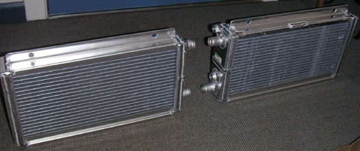
SolidWorks combined with the graphics card lets me rotate the entire model at that quality in real time. With hardware anti-aliasing, texture mapping, transparency, shadows - the works. To illustrate it better I pointed my DV camera at the screen and spun the model around a bit. The resulting video (about 7M in size) gives you some idea of the performance although it's obviously not possible to show the screen quality. Good tools sure make work fun! And I now have my first dp1 video :) 07/27/04 The radiators came in. Exactly as ordered - what a concept! They seem pretty robust, too, despite weighing only 7 lbs each. Cool. (Was that a pun? ;)
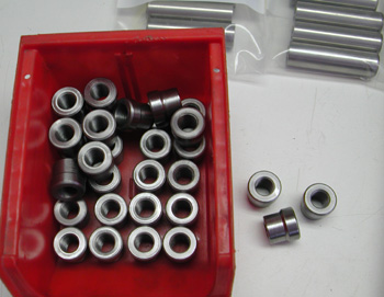
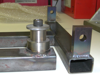
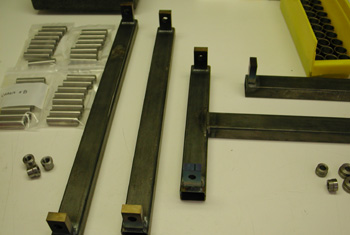
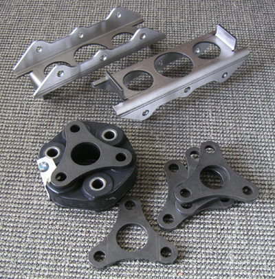
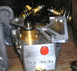
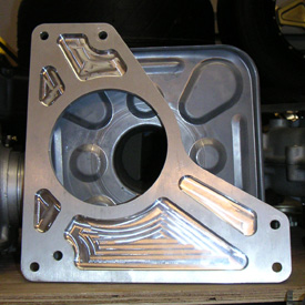
08/03/04 Got the suspension pickup brackets and intermediate shaft drive plates. Pretty cool.
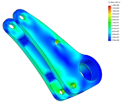
Still finalizing the frame and trying to find someone to build it for me. No luck so far :( I'm contemplating buying a TIG welder and just doing it myself (yeah, I know I'll need some other equipment too). I took a welding class a while back and did quite well - I know I can be good at it. Question is whether I want to... Would certainly save money and time in the long run but short-term might be a different story. 08/09/04 I've been, perhaps belatedly, playing with the Cosmos FEA that is built into SolidWorks. It's a limited version but turns out it is quite useful to get a quick idea of how stressed a part is and evaluate its safety factor in different materials. Below is a sample stress distribution in the suspension bellcrank at 4g load (the part distortion is exaggerated 80x to show the way it flexes):
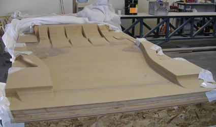
I'm trying to design suspension components for about 8g and the bellcranks should be good for just about that number in 7075-T6 material. The analysis did lead me to consider increasing the rodend size on the upper control arm - the part I originally specified would only be good for about 4g due to bending loads. Since it's a critical component subject to fatigue it would be a good idea to upsize it to 8g capacity. These rodends (NHBB 'racing' ARYT series) are very nice but quite pricey at about $85 each. Fortunately I only need four of the larger parts and the smaller ones which are used in pushrods and tierods are considerably less expensive, while still not exactly cheap. The lower arms use stronger (but cheaper) 'wide' series spherical bearings because they carry spring/shock loads and don't need adjustment for camber. All in all there's about $1500 worth of rodends and bearings in the suspension... Some people build entire cars for that! In other news, the floor mold should be arriving Wednesday. I had the tool CNC machined directly out of MDF board without doing a plug to reduce initial cost somewhat. It should be good for a few parts after which it can be repaired, modified as needed and used to make permanent tooling. It's a bit of an experiment so we'll see how it goes. The materials for making the bodywork molds still have not arrived but should be less than a week now. Waiting for quotes on doing the frame from a couple sources. That should give me an idea of how worthwhile it would be to try and do it myself. 08/13/04 The floor tooling arrived. It's made of laminated MDF board. There is some prep to be done before parts can be pulled from it but things are moving along.
The barrel of epoxy for the bodywork molds also showed up so now it's a matter of getting all the work scheduled and actually completed. Probably won't see first parts until the end of September but the frame won't be ready before then anyway. In fact I still don't have a decision on who is going to make it... 08/28/04 There has been a lot of detail and administrative work but not a whole lot to show for it. Well, the center diff mount plates are done and with the Westie gone all the dp1 parts moved from the spare bedroom to the lift in the garage - it's a lot of stuff, involving a lot of time, effort and $$$$!
The floor and bodywork tooling is being made although it will be a few weeks before I see parts (or even progress, I suspect). Still trying to decide on the frame. Have a couple of quotes, waiting for one more before making a final decision. The fact that a friend is getting an industrial space 10 minutes from my house is leading me more and more towards trying it myself. I've found a TIG welder I'd use if I went this route (Miller Dynasty 200) or if I were to braze the first couple frames it would be that much cheaper and easier to tweak, too. Decisions, decisions... Once the frame is built, one way or another, things will really start to happen. Suspension parts are due soon, too. 09/15/04 Things haven't been going very smoothly lately. In fact I've been experiencing what I call 'high life impedance' (yes, I'm a geek and if you don't know what I mean perhaps you should count yourself lucky ;). All the vendors are dragging their feet and some are acting up unexpectedly. I'm in a constant holding pattern. Tooling for the bodywork might finally get started. Someday. Suspension should be showing up any week now. Machine work is due, oh, just about whenever. I did finally get a couple quotes on the frame and they're VERY different (waiting for a couple more, still). I also found a local CNC tube bending and fabricating company - only to find out they went out of business earlier this year - after 25 years as their web site proudly proclaims... But today I discovered that another local company has acquired some of their machinery and so I'm hoping to get a quote from them one day. They might also be a source of tube bending if I decide to do the frame myself, though I'd rather not since the avalability of the industrial space I was going to rent with a friend of mine is, you guessed it, delayed. Soooo... a lot of waiting, a lot of phone calls and e-mails, a lot of frustration. Oh, and a lot of money too. Even my usually reliable web hosting company just lost all the site statistics prior to yesterday (I'm now getting over 600 daily visitors, about 1.5 million hits a month and 50-60G monthly bandwidth). And it rained for the would-be bike track day, but the sun is out now that the day is done. Cool, I knew this would be fun ;) But then again, I need only take one look at the news, from hurricanes to terrorists to genocide, and count my blessings. If I gotta have difficulties these aren't too bad. UPDATE: Thanks to all for moral support and encouragement - it really makes a difference :) I just re-read the above and it does sound a bit demoralized. It was a downer of a day, what can I say. A downer of a week, really, though nothing I'd describe as tragic. Just a pain. But life goes on and so does the project (however slowly at times ;). On with it then. |