|
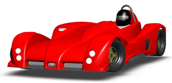
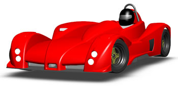
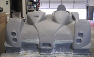
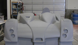
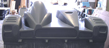
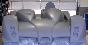
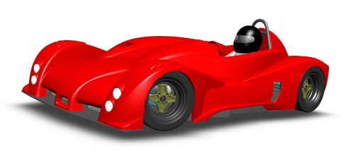
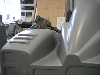
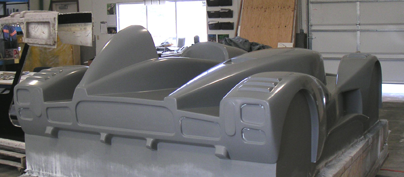
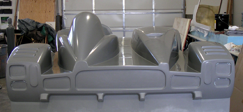
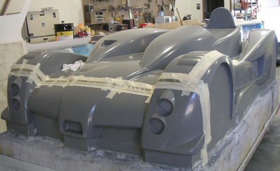
06/07/04 I've been working on a client car project and while designing radiator intakes came up with an idea for a change to my own car. I quickly prototyped it and was pleased with the result. While the change is pretty subtle I think it makes the car look more aggressive (top pic is before, bottom one is after):
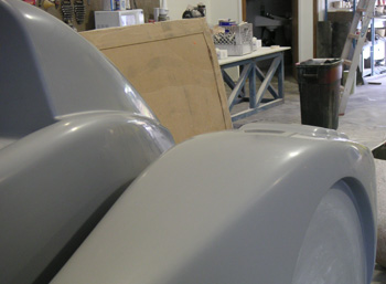
The change is definitely doable although it will take some work and touch-up with primer. Given how much effort has gone into the car already it seems worthwhile to put in a bit more to have it just the way I want it. It's not like I'm in any huge rush with the bodywork anyway. So I'll probably do this tomorrow. It'll also give me a welcome break from wet-sanding which has removed fingerprints on a couple fingers and made them bleed a bit... 06/08/04-06/10/04 Only had a couple hours today to work on the car so I spent them applying bondo to the plug to implement my change. The rough shape is done, now it's a matter of sanding and filling to get it to where it needs to be. Then primer, and if I'm really good (or just lucky) I might get away with one coat. We'll see...
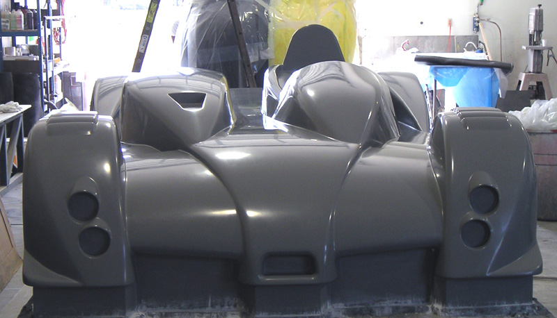
Looks better already. Tomorrow I'll have more time and hopefully will get ready for primer. It should only be needed on the nose and couple small areas where I sanded through with 400 grit. UPDATE: Finished shaping the bondo, then got it primered. Looks like I did a decent enough job with filling all the air pockets that I might actually get away with just the one coat. Today sanded the new primer down to 400 so tomorrow it's time for 600 grit paper. It's getting there.
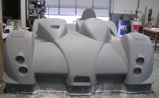
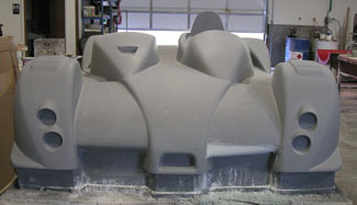
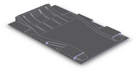
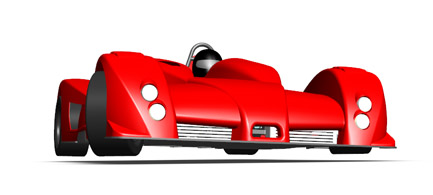
I definitely think the new look is an improvement. Something always bothered me slightly about the old nose and now I know what it was. All better now (glad I figured this out before molds were made - would have been much harder and quite expensive to change then). It basically works as another visual trick to make the car look sleeker than it is. It is only 9" from the front of the front wheels to the very tip of the nose. By comparison, in the MINI that dimension is 12". In other news, finally figured out what I'm doing with the floor mold. Instead of having a plug machined and then making a mold from it I'm having the mold machined directly from MDF board. This is a bit controversial and Janicki put a whole bunch of disclaimers in the quote saying they don't guarantee surface finish or durability. Composites Unlimited guys seem to think that the mold should be good for 2-4 high temp parts and can then be repaired if need be so that a proper mold can be made from it if I want to go ahead with larger quantities. Chances are I might want to change some things at that point anyway so this works out.
The picture shows what the mold will look like - except it will be sitting on a wooden base. 06/14/04 Sanding is down to 1000 grit paper now. There is a bit of a gloss emerging in the surface.
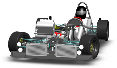
There is some minor touch up of small blemishes to be done, then a bit more sanding, then polishing and waxing. After that I'll start on building the partitions that will separate the mold into five different sections. It's getting there... 06/19/04 Taking a break from the physical effort of getting the plug ready for molds I decided to work on the chassis and frame a bit. Though I have checked the clearances before, the model was not set up the way it should be. So I made some changes to enable examining lean angles and camber control by simply changing ride height at three corners.
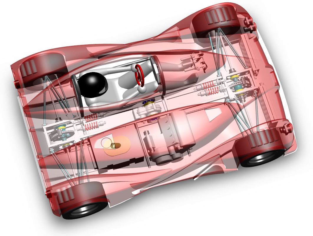
The pictures show maximum lean, minimum radius right-hand turn. It's another verification that camber control should be just about where I want it. Why is the car 'floating' above its shadow? Because SolidWorks has decided that one of the components in the assembly has parts that extend this far down (a cylindrical shape has rectangular extents, for example). It's way too much work to try and figure out which part out of a couple hundred is causing it... 06/23/04 Spent some time yesterday watching a stock Hayabusa motor running on an engine dyno at Loyning's Engine Service, a well-know race engine shop that happens to be here in town. The motor performed quite well putting out around 175 hp at the output sprocket, with a broad and flat torque curve of around 100 lb-ft. Very impressive for a 1.3L beast :) Loyning's will probably the outfit I'll go to in order to get my motor dialed in, since I'm planning on doing at least a custom intake and exhaust and maybe a turbo (still undecided on that but leaning strongly towards it - a nice ceramic-bearing T3/T4 hybrid unit from Turbonetics running at a mild 4 psi with stock compression)... While my mind was on engine matters I finalized the radiator design and ordered a pair from Howe Racing. One issue was figuring out the mounting. Each of the rads will hang in two rubber grommets attached to a horizontal tube that will bolt to the front of the chassis. The bottom will sit on top of a foam rubber strip glued to the undertray. Should work.
The other issue was deciding how to run water through them. I went with a double-pass design with water entering and exiting on the same side of the radiator after 'looping' around the other end. This provides more efficient cooling than the traditional 'diagonal' flow designs. The radiators are pretty small, measuring 18" wide by 9" tall. However together they add up to a fairly large 18"x18" single radiator of 4-pass configuration which should be more than sufficient. Water will enter the bottom of the right radiator, then go from the top right tube to the top left tube and then return to the engine from the bottom left tube. Pipes will be routed underneath the raised backbone frame and cooling air for the front brake will be ducted between the rads. Another engine matter that's been causing me some grief is the mount design. I've finally decided to make a small subframe which will hold the engine, the drysump tank, the oil-to-water intercooler and all intake and exhaust plumbing. The entire assembly - call it a 'power pack' - will be rubber-mounted to the chassis. This way the engine can be removed as a unit with minimum effort and a variety of engines could be used in the same chassis just by making specific subframes for each type. The Hayabusa by being the largest motor I'm likely to use will serve well for defining the assembly sizing. While on the subject of engine sizes, I looked at an '04 R1 motor that was out of the bike. The thing is sweet! Very compact and much lighter than the 'busa - I had no trouble lifting the whole unit by myself whereas the 'busa at its 180 lbs is a bit of a stretch for me to do that. I'm guessing the Yamaha is at least 50 lbs lighter and supposedly puts out the same power! After the engine mount is finalized I'll be able to go get that made. Then I need to finalize the mounts for all 3 diffs and the chain tensioning mechanism. After that I can finally finish the frame and set about getting that fabricated as well. The floor mold is due in the beginning of August and realistically I won't have bodywork molds until then anyway. So with much luck and effort I could conceivably be ready to test the car by the end of August. That's when the next Lotus track day is which would be a great test venue for the dp1. So it's a good target to shoot for. Ambitious, yes, but gotta have goals :) Looking at the model it's scary how much detail work has gone into it - almost as scary as the realization of how much is still to come. Some companies have vast engineering departments doing this kind of stuff....
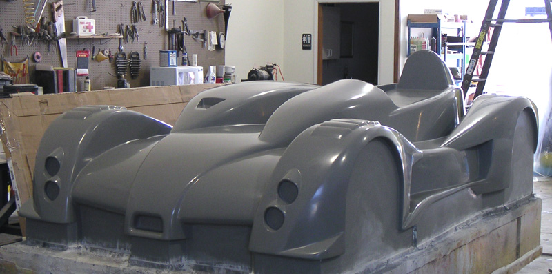
06/24/04 Back to working on the plug - now the sanding is done and just polishing and waxing left. After that the mold fences need to be built and the mold itself will be constructed. I've been trying to choose between cheaper but less stable vinyl-ester mold and higher quality but more expensive epoxy kind. Finally decided to go with the latter. Given the amount of money this project is taking up already, the difference in cost (about $3K more for the epoxy in materials and maybe another $1K in extra labor) is not all that huge and I'll have a much better tool as a result. The plug is starting to look pretty shiny in the meantime...
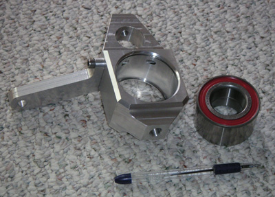
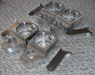
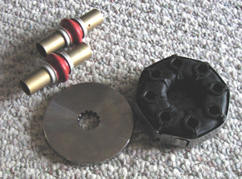
On the way back stopped by and picked up a first-article prototype upright and steering arm from Jon Axt. The parts are very nicely made and the bearing bore is exact. Heating up the upright in a toaster oven to 350F lets the bearing slip right in. The prototype is 6061 alloy but actual parts will be made from 7075.
The upright and steering arm together weigh about the same as the bearing - around one pound. Besides the shrink fit the bearing is retained by a flange on the high-load side and a snap ring on the low-load side. The steering arm can be bolted to either side of the upright making the parts universal - they are identical at all four corners. Not having to deal with brake loads or brake heat at the wheels definitely simplifies things! Jon will be making a number of other parts for me, too. It's great to finally find a good resource for that. 06/25/04 The sanding and polishing is done. First coat of wax is on (out of 7). Shiny....
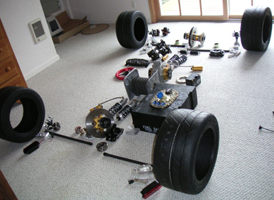
Click on each picture for larger version. Much work accomplished, much remains. 07/03/04 Got the uprights and steering arms. They still need to be anodized but I'm going to wait until I have more parts and do them all as a lot. And speaking of parts, the pile in the guest bedroom is growing... :)
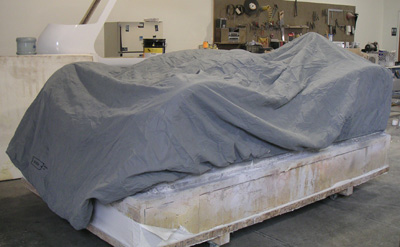
I'm now working on a mounting method for the center diff. I really wish I had figured out my next-generation drivetrain earlier. This thing is HEAVY and expensive, too. Live and learn. At least when I build chassis #002 with the new drivetrain I'll be able to compare them back-to-back. For the past few days I've been working on building mold partitions - nothing too exciting. The picture below shows the lines marked out with tape and quick fiberglass 'splash' molds that help me transfer the curves to 3/4" thick wood for the partitions. The lines were projected onto the surface with a laser level from Sears - pretty neat tool especially for the money. Thanks to Kurt for bringing it to my attention. Also, since the plug is now polished and waxed I got a cheapo car cover to protect it. Looks pretty mysterious with the cover on :)
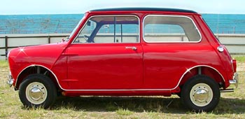
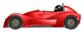
07/06/04 Don't know why I hadn't done this sooner, but today I looked up the dimensions of the original 'classic' Austin Mini on the web. I was amused to find out that the dp1 is almost identical in some dimensions but is quite different in others...
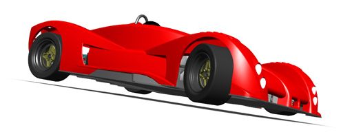
So yes, the dp1 is an inch shorter nose-to-tail than the old Mini and has a fractionally longer wheelbase. Looks a little sleeker though :) 13" wheels sure look big!
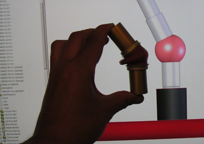
Meanwhile, back in Scappoose work continues on partitions for the molds. The partitions will be done Thursday, installed Monday and first mold should be started Tuesday. A bit behind schedule but so it goes. 07/10/04 Progress is pretty much daily now but I'm waiting a bit between updates, otherwise it can get out of hand pretty quickly. The focus right now is on detail work - taking care of all the little things that make a big difference. For example copling the Hayabusa output shaft to center diff/revbox input shaft. Splines are a pain to cut if you don't have the right broach so I ended up just calling Sprocket Specialists and had them make me some 'blank' front Hayabusa sprockets with the splines cut but no chain teeth. This was surprisingly quick and inexpensive (3 days, $20 apiece). Great company to deal with. Now once I figure out exactly what I want to bolt up to the pieces I can have them machined to suit. Picked up a rubber driveshaft coupler for a BMW 2002 but I'm not sure that the 8-hole design is ideal for me (limits flexibility). I might change to a 6-bolt one from an E30 3-series. Decisions, decisions. Also got the Apex U-joints for the steering linkage then designed the linkage itself.
After tilting the steering rack 10° I got the shaft to clear the frame rail by over 1/4". The U-joints are operating at 25° and they are rated for 35. A quick low-tech visual check confirms that they will in fact do the job.
Now I can design the steering column mounting bracket, the steering rack mounting bracket and the frame bracing in the general area, now that I know what it needs to clear. Also I need to make a choice on the bearings for suspension bellcranks so I can finalize the design of those and get them made as well. People often use needle bearings in bellcranks, with either a separate thrust bearing or just teflon thrust washers, but I'm leaning towards sealed ball bearings instead. They are plenty strong for the forces involved and carry both radial and thrust loads quite well. Just need to find a good source so I can price the various options and make a choice. Speaking of the frame, I placed the order to have suspension pickup brackets laser cut and CNC bent. Turns out this is quite cost effective. I was going to get a quote for making a machined aluminum version but I already know there is no way the price can even come close. Since there are 8 of these brackets per car it tends to add up quickly! The cool thing is that they will precisely locate the suspension pickup points and will provide a large degree of self-jigging for the rest of the frame. Yes, I'm designing this for manufacturability.... Lessons learned in the electronics business :) Overall the design process is an iterative one - do the concept, flesh it out enough to see the issues, adjust or discard, repeat. |
|||||||||||||||||||||