|
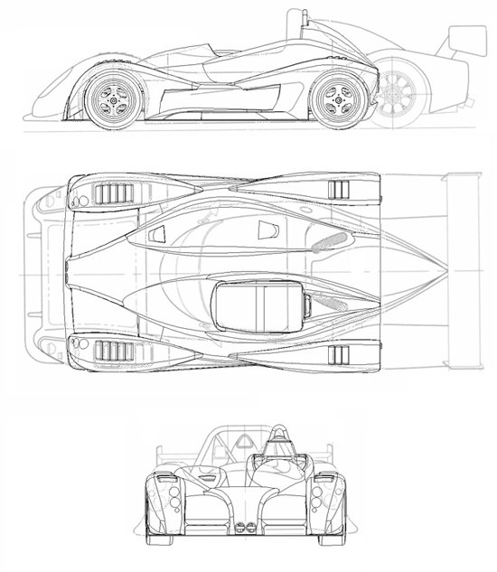
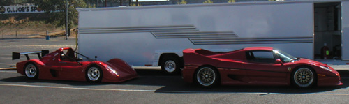
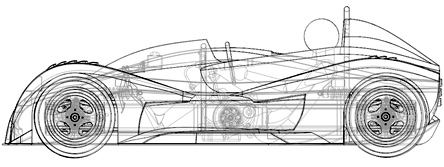
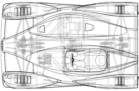
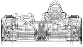
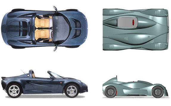
07/24/03 Recently I found a dimensioned drawing of an SR3 on the Radical site, so I scaled it and overlaid the dp1 for a size comparison. Interesting how some dimensions are nearly identical (purely by coincidence - or rather because it makes sense to do it that way).
As seen above the Radical is not a big car itself - so picture dp1 next to it :) I've made some good progress on the chassis, switching to square main tubes and thereby solving my suspension bracket dilemma. I now have plenty of weld, a degree of self-jigging, ease of fabrication and still clear the chains. Also decided using sheetmetal plates for mounting the diffs, with chain adjustment provided by a stop nut much like on a motorcycle. The four tubes only weigh 6 lbs more combined than the round equivalents but make fabrication and design significantly easier.
Taking a break from all the chassis work I tweaked the bodywork a little more - partly so that the headlights will have a better chance of clearing the front wheels (I intend to use small Hella projector units). The body design is pushing SolidWorks to the limits, and in a few cases moving a spline point by as little as 0.05" makes a lot of features fail. So it's a bit of a juggling act. Another item I changed was the addition of small 'dive planes' on the nose. Should help both aerodynamically and aesthetically (probably more the latter but one never knows).
The task is still looking daunting, but I'm getting it under control little by little. It has certainly come quite a ways from this:
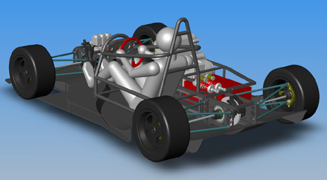
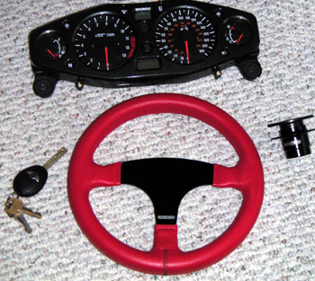
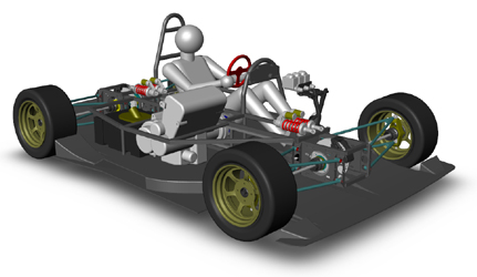
07/27/03 As I continue to work on the chassis I'm having to finalize more component choices and get them into CAD. Chose a standard 8-gallon fuel cell from FuelSafe and a 10.25" steering wheel from Racetech (same one as used in the Westie, very light and one of the smalles wheels out there). Created the CAD model for the Ohlins ST44 shocks with 100mm travel and the stock Hayabusa dash. I can even verify gage visibility through steering wheel :) Spent a lot of time in the garage measuring the positions of various components relative to each other and the driver in the Westie and the Elise. It's great to have ready references.
I now have most of the major components in CAD with fairly accurate weights. I'm guessing there's another 50 lbs worth of stuff that I've left out. But so far, with 8 gallons of fuel and 185 lb driver onboard the car ends up at just a hair over 900 lbs total, with weight distribution 45% front / 55% rear and lateral CG only 1.25" from centerline (this would change a bit with less fuel). So It looks like I'm still on-target weightwise. At least in CAD. For fuel system I've decided to use a small header tank with the stock Suzuki in-tank fuel pump and its integral pressure regulator. The tank will be fed from the fuel cell by a low-pressure fuel pump with excess returning back to the cell. This setup should eliminate any fuel starvation in turns and should permit the maximum use of all onboard fuel. This was an issue in the Westfield recently since now that I'm going quite a bit faster in it, I've been getting fuel starvation in longer turns even with half a tank remaining! 08/06/03 Haven't worked on the project for a few days due to some electronics work that I have to do, and looks like I won't have time for another couple weeks at least. So I thought I'd post an update with what's been done to date since the last one. I re-examined the SCCA rulebook with respect to rollcage and found something I had previously missed - that all bends must be at least 3x tube diameter. Which means my main hoop needs to be bent at 4.125" radius rather than 2" I had intended previously. This led to a rethink of the rollcage and its bracing, and subsequently yet another redesign of the bodywork in the cockpit area - a tedious process due to marginal ability of SolidWorks to cope with all the curves. I'm getting better at recognizing features that it would have trouble with and so was finally able to get it to rebuild with the new dimensions. Acutally looks better to me now than earlier version (although most would probably be hard-pressed to spot the differences).
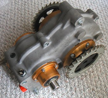
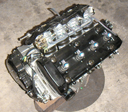
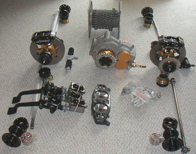
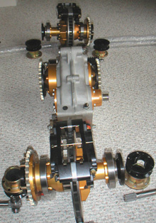
Also did some calculations on the halfshafts since they are being used to transmit brake forces as well as drive. Windup may prove to be an issue - we'll see how much of one in actual testing. In a 1.0g stop the front shafts are stressed to 37% yield strength and twisted 10° which probably is not going to cause TOO much of a problem. A 1.5g stop goes to 63% yield stress and 18° which is a bit more problematic but still reasonable. A 2.0g stop pushes things to the edge with 94% yield stress and 27° twist in the shaft. At this point each front shaft will see 575 lb-ft of torque! The calcs account for effects of weight transfer and assume 900lb gross weight and CG height of 13" above ground (which is what SolidWorks tells me it is with driver and fuel). At 1.0g the front is doing 61% of the braking, at 2.0g it's 77%. The rear axle actually has slightly less brake torque on it at 2.0g than at 1.5g. Interestingly, dropping ride height from 3" to 1" (which would probably be the case in any situation where 2.0g braking is even a possibility) the numbers at 2.0g drop to 72% front bias, 88% yield stress and 25° windup on the front shafts, all due to reduced weight transfer. There are going to be some pretty complex interactions between the Quaife diffs, chains, brakes, tires and halfshafts. Hopefully it won't get TOO ugly. I can reduce shaft twist by half by going from 3/4" OD to 7/8" OD at the cost of some two pounds per shaft (8 total). It won't improve ultimate strength though because of the splines which require a 3/4" relief at their base. So if I need stronger shafts I'll have to use larger CV joints and then the whole thing gets a lot heavier - but stiffer shafts are easily doable. I guess testing will show how much of an issue this is. As a backup I have a design for a mechanical airbrake for the back (activated by brake torque) which would both help braking and keep more of the weight on the back. Illegal for racing, of course, but should work well for track days. The preferred solution would be to reduce weight and lower the CG, which will be a big part of the development process. One interesting thing to look into would be having carbon wheels made - this could save as much as 20 lbs or rotating, unsprung mass (thereby helping keep tires on the ground and reducing any wheel hop associated with shaft windup). In 13" diameter this shouldn't be too outrageously expensive. While on the subject of numbers, I've found that most race cars out there have wheelbase-to-track ratio of around 1.6, give or take. Mine is more like 1.25. The theory being that this should favor cornering over straight-line stability and hopefully result in faster overall lap times at most venues while keeping top speed reasonable (gearing-limited to 160 mph). If one looks at the percentage of time spent at TOP speed vs time spent in corners, it seems obvious that a small gain in cornering speed will offset a fairy large drop in top speed. Shifter karts have an even lower wb/t ratio and seem to bear this out with lap times similar to a well-driven Viper on race tires at PIR. 40 hp and 125 mph top speed matches 500hp and 160 mph top speed. Seeing karts in the corners shows why. So this is my hope - to maintain higher corner speeds. This would relieve the brakes quite a bit too. As an added bonus a wide, short car has a better 'aspect ratio' aerodynamically than a long narrow one making for more efficient generation of downforce. Or at least that's the theory.... 09/09/03 Well, finally after all the months of waiting the modified center diff / reversing box is here. Modifications consist primarily of custom output flanges and new side plates incorporating extra bearings to support the flanges against chain tension loads. Hopefully the casing will prove strong enough, although I have some ideas that I will explore for reinforcing it just in case.
On the scale the box comes in at 51 lbs, about 10 lbs more than I had hoped for. But such is life. Eventually I'll have to re-engineer much of the drivetrain anyway. For one, I'd like to see if I can replace the center diff with just a sprag clutch - the front wheels will never be turning slower than the rears, and it would actually allow a small degree of slip at the back - the tighter the turn, the more rear slip. The only issue I can see with a sprag approach is that the fronts would drag if turning while reversing. In a track car I think that would be acceptable. But first I need to finish the car as-is and do a lot of testing. I'm designing the chassis so that I can try using belts in place of chains, too.
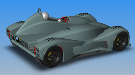
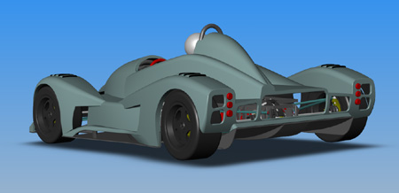
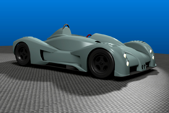
So now that all the major drivetrain pieces are here it's up to me to finish the chassis design and get it made. We'll see how quickly I can accomplish that... 09/27/03 Yesterday I went to visit Lee Stohr to see his new operation and check out the development he's done on his cars since the last time I was there. Lee did 'quite well' at the SCCA runoffs a couple of weeks ago, with his cars taking top 4 spots in DSR. He must be doing something right... We chatted for a bit and I got to sit in one of his cars. One thing I realized is that the driver is far more reclined there than what I was planning on - and I rather liked the driving position. So I went home and made some changes to my design - reducing the overall height by 4", dropping CG by quarter inch, and I think improving the looks overall as a bonus. The car is now 39" tall to the top of the rollbar and exactly 3 feet to the top of driver's helmet.
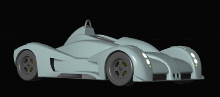
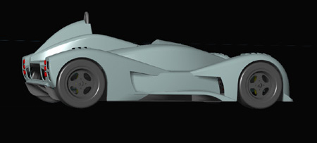
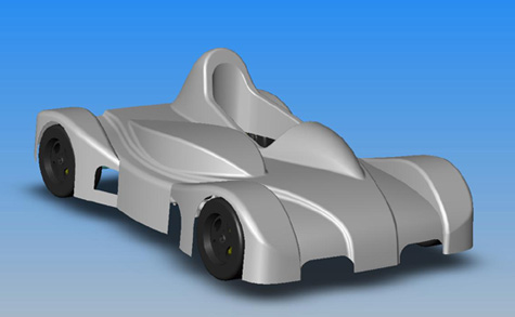
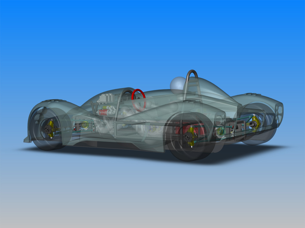
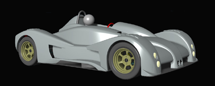
Also did some renderings of the new shape while contemplating whether to enter Solidworks design contest (I might - I have two more days to decide, although since the design is not final I don't have very high expectations). The renderings came out pretty neat though (click on each picture for a larger 1024x768 version).
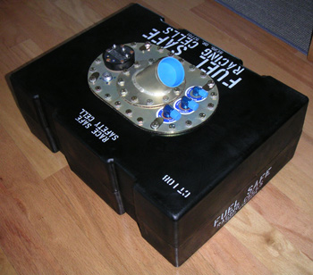
Also, a couple of days ago the fuel cell came in. I went with a 'circle track' polyethylene one, expecting to enclose it inside the frame tubing for protection. The complete 8-gallon cell, with built-in scavenge pump, collector, level sender and some other fittings ends up weighing just 14 lbs. Not too bad. My plan is to have a small header tank mounted next to the engine which will contain the factory high-pressure pump and regulator. The low-pressure scavenge pump from the cell will feed the header tank with the excess returning to the cell. This should allow maximum use of onboard fuel and prevent any starvation issues like I'm having on the Westie.
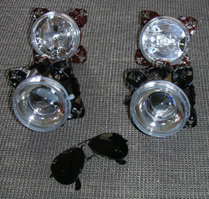
The headlights arrived as well. I'm using Hella 90mm halogen projector units. Pretty cool...
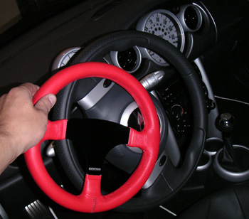
The immediate task is to finish the frame and overall chassis design, get final quotes, select a vendor and get going on fabrication. It's harder than it sounds... 10/01/03 The steering wheel from Racetech in England came in. Very cool, just 10.25" in diameter and very light (you can see how small it is in comparison to the wheel in my MINI).
Also got a quick release adapter to go with it. Except the adapter doesn't include the matching shaft part. Am I missing something, or is there a spec for how the shaft should be machined? Will e-mail England and see what the deal is... Nothing is ever easy. UPDATE: E-mailed the vendor and indeed they had left out a part. They're sending the missing piece. Nice to see good service and prompt response - it's the next best thing to getting it right the first time. 10/11/03 Now that I actually have the headlight units I got them into CAD. Predictably, they don't fit the way I had originally intended - the front wheels hit the backs of housings. So I had to spend some time moving the lights forward and down and coming up with acceptable bodywork design to accommodate the new position. Came out OK I think.
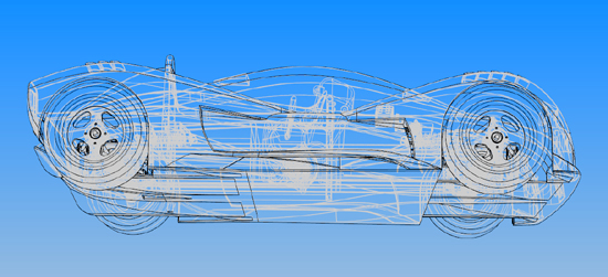
Of course the lights don't meet street legal minimum height requirements - but I expected that. The required minimum for low beams is 24" off the gound, and mine are 16". The high beams are just 11" off the pavement. With all that, I'm quite happy with the fact that I've managed to keep the lines fairly proportional. It's hard to tell from the pictures just how tiny the car really is. The top of fenders is 23" above the ground, and the very top of the rollbar is 39" tall. While spinnig the design around in wireframe mode I happened upon a view that I thought looks particularly neat. So it's included here for no reason other than that:
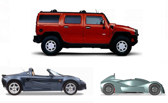
I need to start making more progress. Still don't have a vendor for most of the fabricated parts, although have some new leads. At least the missing part of the quick-release steering adapter came in from England. 10/19/03 There was a discussion on one of the car forums about the size of the Elise and how it's too small for some people. This prompted me to do a to-scale comparison of the Elise and the dp1.
Obviously anyone who finds the Lotus small won't appreciate the dp1! To me the Elise is on the large side for a sportscar, so after looking at the picture I'm even more excited about my design :) Then on a suggestion I also included a Hummer H2 in the picture... Enlightening.
10/22/03 A couple of days ago I created the file for the 'plug' for the bodywork from which the moulds will eventually be taken. The file has now been sent to Composites Unlimited so they can get some firm quotes on making the plug, the moulds and the bodywork itself.
In some cases the plug can be made by hand from patterns plotted on large sheets of paper. In the case of dp1 there is so much detail and fit is so critical that the only practical way to do the plug is on a 5-axis CNC machine. The process is similar to that used to make fiberglass boat hull plugs. Some structural foam is set down in the machine and milled down to about 1/8" below the desired surface. The part is then covered with a thick layer of epoxy (usually fiber-reinforced), allowed to harden and then machined to final shape which is accurate to about 1/16" of an inch or better over the entire surface. From that a multi-part mould will be taken which can then be used to make bodywork itself. The current plan is to have the entire body as one piece. It will consist of 2 layers of pre-preg e-glass with some local reinforcement. Solidworks tells me it should weigh under 40 lbs. Making the mould is the most expensive part of the project. Exactly how expensive remains to be seen though I do have a rough idea.... The whole process will take several months. 10/28/03 The 'upside' of vendors dragging their feet is that it gives me more time to ponder what exactly I'm doing. And in this case I've decided that the halfshafts and CV joints I was going to use are not up to the job afterall and I need to do something different. This came about in an indirect way. I've known about the marginal nature of the design ever since I did the calcs, but already having the parts I was willing to just try it and see how it goes. Then I was browsing around for wheel choices and found an excellent wheel made by Rays/Volk - the TE37 'drag' wheel in 13x8 size. Apparently it is used in FWD dragsters to reduce rotating inertia and get a taller sidewall for better grip. The wheel is just the right size for me and only weighs about 8 lbs. It is not outrageously expensive, either, at around $300 apiece. It is available in a nifty bronze color and has a clean 6-spoke design. The only issue is that it comes in a 20mm offset. I had originally intended to use 48mm offset wheels. Switching to 20mm would require halfshafts that are 1.5" shorter. Which is actually a good thing since it would make them a little stiffer. And the uprights would be simpler/cheaper/lighter. And the wheel itself is stronger. Steering linkage is also easier with more travel available. All good. But if I'm going to get new halfshafts might as well beef them up too. And get outer CV joints with more angle capability for steering (the originals were only 22 degrees, much less with boots). And so it was decided - new parts will be lightened VW outer and inner CVs and custom 22mm shafts.
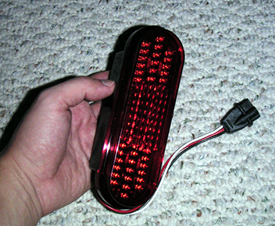
There will definitely be a weight penalty but I don't think it will be huge, maybe 5-8 lbs. I can return my current CV parts for credit and maybe someday someone will want my existing halfshafts... If not then so it goes. Now I need to finish designing the new uprights, various remaining suspension parts and the frame itself. As added motivation, a fellow builder whom I've been corresponding with for a while e-mailed me today with video of his first-ever drive in a car he's been designing and building over the span of several years. Way cool - congratulations, Kurt! :) I've got to get myself moving here... 11/05/03 Progress is slow. Spent quite a bit of time redoing stuff - now that I've chosen to use different CV joints and halfshafts a number of things had to change. New parts have been ordered and old ones sent back. Also received the nice oval LED taillights that I've decided to use. They are quite bright and draw almost no current. I like the look better than separate round ones I was planning on using before.
Also took the opportunity to check for front wheel clearance (I have enough for about 30 degree steering angle, which is plenty with such a short wheelbase). While tinkering with that I tweaked the profile of the front fenders slightly. It's a subtle change but makes it look sleeker to me.
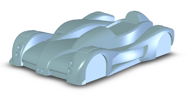
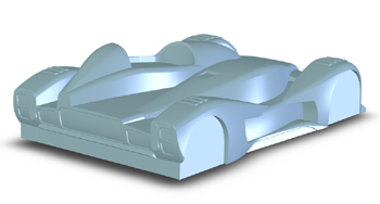
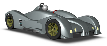
Now on to the somewhat dreaded task of finalizing the frame. It's a lot of detail work and it is quite a challenge to make sure that the frame is the lightest possible while carrying the loads and clearing various components. There's also a 'minor' issue of ensuring the frame is manufacturable. 11/07/03 Kept messing with the light placement and front fender contours. Just wasn't happy with how close the bulky high beams are to the wheels (less than 1" clearance). Tried quite a few variations and finally ended up moving the high beams out of the wheelwells and moving the more compact low beams lower and forward. Not ideal placement but it's not like the car is going to see much night duty anyway. This also allowed me to further slim down the fenders. The new look is rather, uhm, 'distinctive', but I like it.
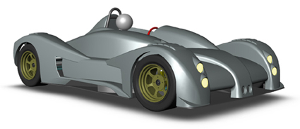
Compare this with previous version below:
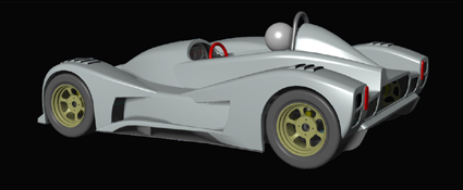
To me the new one looks more interesting and more aggressive. It's probably more aerodynamic too, although from standpoint of light functionality the old one is more effective.... Never a shortage of design choices or decisions to be made. UPDATE: For a reality check I've asked for input from fellow car enthusiasts (isn't Internet great?). Got some very good comments, thought about it for a while and came up with the following:
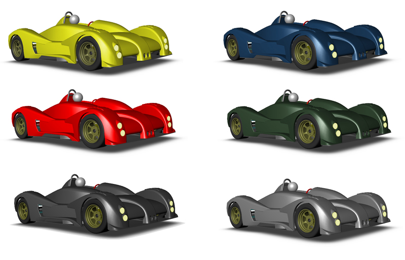
The lights are moved down and forward as needed for clearance, they are closer together to make them appear more like a single unit, and they are more centered in the fenders with the upper lights being slightly farther apart. As someone pointed out it's possible to tinker with this forever so I'll just leave it alone for now. This looks like a good enough compromise between functionality, physical fit and cosmetics. It's even OK in red (some might notice the subtle changes in the nose and helmet fairing on the red car vs the silver one above - I can never stop tinkering ;).
|