|
10/30/02Well, pretty much all of the Hayabusa parts have been sold on e-bay. Turned out OK, as when all is said and done the brand-new motor with all the electronics, dash, etc., ended up costing me around $4200. Learned a few things in the process, and I think this would actually be a feasible way to do low volume production - just buy the bikes and part them out. In the meantime, the driveline design has been evolving some more. Finally received the Quaife center diff, and found a good source for front and rear diffs that allow the chain or belt to run on the side of the frame. The same company (TRE in Texas) will hopefully help me with some component design work and fabrication. About 20 years ago in college I had an idea of an AWD system using Torsen diffs with braking applied to the diff, and the brake torque actually being sent to the wheel with the most traction automatically. Lo and behold, TRE is doing exactly that with their differentials, although up to now they've only done rear wheel drive - but apparently the concept works really well. So my plan is to have just two diff-mounted brake rotors, one front and one rear. Light, efficient and elegant.
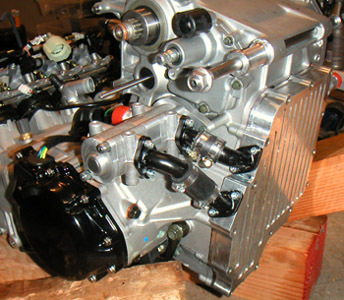
There is quite a bit of work to do on driveline design. The suspension design is moving along, and I also need to order the dry sump components from England, now that I got some money back out of selling the bike parts... 11/25/02 There has been quite a bit of progress on the design, although none of it is visible yet. I've recently placed a big order for most of the drivetrain components, which will take a few weeks to arrive. Also refined the backbone chassis design quite a bit after ongoing discussions with my vendors. The one tangible bit of progress is that the dry sump kit arrived from TTS in England, so now I need to install it on the motor.
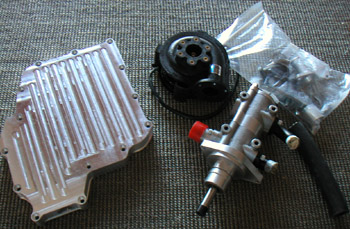
I like this one better than the setup supplied by Westfield because it drives the oil pump from the original waterpump shaft (as opposed to a cog belt from the crank), and replaces the water pump with an electric one. This has a number of advantages, including the ability to run the waterpump for a while after engine shutdown to prevent heat soak. It also avoids the horsepower loss and pump cavitation at high RPM and still provides full cooling at idle. The oil pan is about 1" shallower than the Westfield one, also (more ground clearance) and is a neat CNC machined part intead of the rather porous and crude-looking casting I got with the Westie. So things are moving along, if slower than hoped for. On the plus side, these days I have a lot of free time and should be able to spend much of it on the design. The slow part is waiting for various vendors. 11/30/02 I recently found a very informative website dedicated to D Sports Racers (DSR) cars and technology. In perusing it I was amused to discover that I'm not the only one thinking along the lines of a supersized kart. A company called traXstar appears to have been working on something along these lines for a while (but still only rear wheel drive, which doesn't address the biggest problem of superlight bike powered cars - PUTTING THE POWER DOWN). They even went as far as to get a patent on the layout - which is an interesting lesson in relative futility of most patents (something I've learned the hard way having 7 of those to my name). In order to distinguish their layout from a common kart, which also has the engine sitting beside the driver, they had to narrow the claims to the point where they are very easy to circumvent, and end up limiting their own design options. The most important of which is the condition of their patented layout to have a chain or belt aligned with the chassis centerline (which is not really desireable anyway) since karts have it offset, usually to the right. What this means is that someone who offsets their chain or belt to either side of centerline is free and clear. As is anyone who does not use a chain or belt (but use a driveshaft and orient the engine longitudinally, like the initial dp1 concept). Ah well, I wish traXstar luck just the same - anyone who successfully turns a dream into reality deserves applause. It is also encouraging to see that they've apparently succeeded in hitting a 750lb weight, which means I'm not too far out with my targets. In other news it seems the dry sump pan was not finished properly, so I had to send it back to England for rework. Sigh.... 12/8/02 Received some CAD data from TPE on the diff configuration. The file imported into my SolidWorks program pretty well although it did require some massaging. Looks pretty cool!
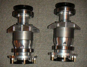
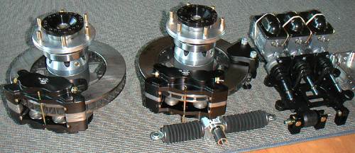
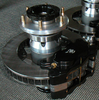
Now I can get moving on designing the mounting plates. The diffs should be arriving in a couple of weeks. Halfshafts are getting custom made because of their length (24") so that will take a few more weeks. Also decided to go with an integrated Quaife reversing box and center diff to eliminate the central chain. Of course the standard box will need modifications and custom flanges to drive sprockets for the chains to front and rear, and it will also need custom gearing. The good thing is that all of this is doable, with the obvious downside of BOTH time and money. But gotta do it right. I finalized the choices of most braking components and placed the orders yesterday. The rotors are 10.25" vented front and rear, the front one being 1.15" thick and the rear 0.75". Four-piston calipers at both ends, of course, with a separate mechanical parking brake caliper for the back. Hopefully this will provide adequate braking for a car this light. 01/02/03 Some of the parts are starting to come in. The dry sump oil pan came back from England, finished this time. Except that they promised to add a fitting for standard oil cooler hose and forgot. Ah well, I somewhat expected that. The diffs also showed up.
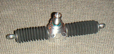
After some suggestions and research on the web I got a small steering rack made by Stiletto for Junior Drag cars. The design is not ideal (too much travel and ends are not very well supported), but the price was OK and it will do to start with.
Still waiting for a lot of brake parts which are supposed to be here next week, and a lot of other drivetrain components which will arrive at some time in the future... Of course they are all paid for already. The lead times on some of the custom stuff can be pretty long. I'm getting the feeling that the first pass at this car building stuff is going to be less than ideal if it is to get done at all. Just got to accept some compromises to make a prototype and refine from there. Which also means this is going to be a lengthy and expensive endeavour (and is well on the way in both regards already at 6 months and rapidly closing in on $20K before any really tough work has even began). But I knew that going in. 01/17/03 The brake parts finally arrived. Little by little things are coming together.
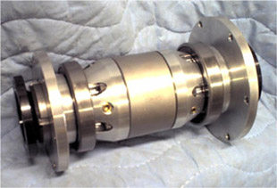
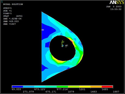
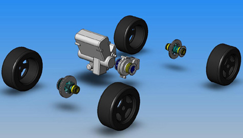
Each complete assembly, with diff, bearings, flanges, rotor and caliper (2 in the back) weighs 27 lbs. This is 3 lbs more than my spreadsheet shows, most likely because the 14 lbs for diff weight that I had probably didn't include some parts. Each diff assembly complete is 17 lbs. Overall the weight is pretty good - considering that the Cosworth shaft-drive diffs I was originally thinking of using weigh 30 lbs, WITHOUT flanges or brakes - and they would have required double the number of brake components! I had TPE do a stress analysis on the brake rotor mounting setup. The results showed some deformation at a little over twice the expected maximum load, but I hope it will hold up under any use that I'm likely to subject it to in the first few months..
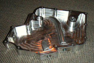
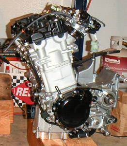
I suppose I really had to draw more on my experience developing electronics of all kinds. With so many new things and unanswered questions, it has to be just a prototype. Design it enough to build, test, and modify, then evolve from there. At this point I don't even know what kinds of issues I'm going to run into with AWD chain drive and other driveline bits, as to my knowledge nobody has done this kind of setup. Not in the last 50 years anyway. And even having lots of experience doesn't guarantee freedom from problems - just look at all the recalls issued by most major manufacturers. Having accepted that I'm building a prototype and not a finished product I feel quite a bit better, actually :) Somewhat unrelated, I dropped by Composites Unlimited today, the people who make Stohr bodywork. I had them make a custom panel for the Westie and they'll be the ones making dp1 bodywork when I finally get to that part. The really cool thing is that they are also making all the composite parts for Viper Jet, a homebuilt fighter-style jet airplane that I fully intend to build some day - probably start 1-2 years from now. The builder-assist program takes place right here in Oregon, just 30 miles of twisty roads from my house. Doesn't get much more ideal than that - must be fate! :) They had a couple airplanes under construction but I neglected to bring a camera. Next time I definitely will. 01/19/03 Finally drilled and tapped the holes for the oil cooler hookup, got some stainless fasteners and installed the dry sump pan on the motor. Looks pretty neat.
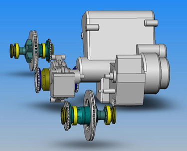
I do like the TTS setup much better than the Westfield supplied one I have in the Megabusa. The pan is about an inch shallower and there is no belt or messy bracket for the oil pump. I also like the idea of the electric water pump because it doesn't steal power at 10,000 RPM. There was an issue with the pan not being finished, but to their credit TTS realized it and were proactive and prompt in fixing the problem. Good customer service and no harm done so I'm happy, especially since in my opinion design-wise it's a superior product. 03/06/03 Well, things are going quite slowly. The diffs had to go back to TPE because I want to have all exposed parts either anodized (almunium) or plated (steel) for corrosion resistance. The center diff/reversing box finally arrived at TPE from Quaife and the support bearing carriers are being designed, along with custom drive flanges. Now that I have some dimensions for all these parts I can make some more progress on the CAD.
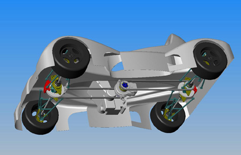
Because the center box is a bit different from what was anticipated, I had to turn it around and switch the front chain to the right and rear chain to the left. This actually works out quite a bit better anyway, so I am happy. The center box input shaft also ligns up perfectly with the engine output shaft, so the intermediate driveshaft will run in a straight line and help driveline efficiency. While waiting for the other parts I have conceptually changed the way the chassis is going to be built. The new plan is to have the backbone be made from carbon/nomex core composite as an Omega-shaped center tunnel, which then gets rigidly bolted to a carbon/nomex structural floorpan to form a very stiff and light torsion tube from which everything else hangs. The chains will run outside the tube and will be enclosed by composite covers/guards. I would like to seal the covers and run the chains in oil for longer life and better efficiency but don't know how practical that is. Will have to wait until more details are finalized and modeled in 3D. I'm currently working through hardpoint attachment methods (FR4 inserts) and all the serviceability access issues. Some components will be easier to access than others, but overall I'm shooting for an order of magnitude improvement over the Elise :) 03/07/03 Doing some more CAD. SolidWorks is a wonderful tool, really. I've been messing around with chain design, and determined a couple of things. First, the sprocket flanges on the diffs need to be machined down a little bit for chain clearance. Since the diffs are apart at the moment it's fairly easy to do right now. Not the kind of thing I'd want to find out when everything is anodized, assembled and in the car. Second, I've found that by reducing my wheelbase to 79" from 80" I can use the longest available 'pre-cut' chain at 156 links - front and rear. This would avoid all the mess of buying bulk chain, splitting it and then riveting the links. Easy to change in CAD, would not be that easy in carbon.
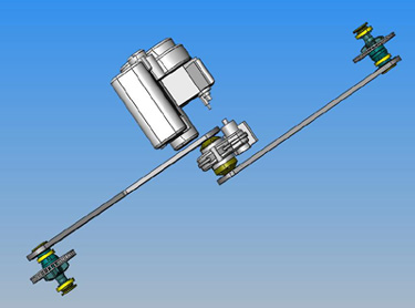
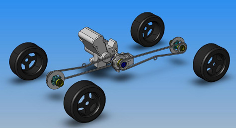
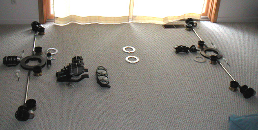
I'm planning to use Tsubaki Sigma 530 chain, commonly used on drag bikes. It has 10,600 lbs tensile strength and very good wear characteristics (it is a sealed O-ring type design). Each of the two chains is roughly 8 lbs and costs around $150. Tensioning will be via slack-side idlers, I think. As I get into the details of suspension pickups and diff mounts I might consider movable diffs instead, but it would require accommodating positioning the calipers accordingly since the rotors are diff-mounted. We'll see. There is no shortage of choices and options... 04/17/03 Finally received many of the parts that I had ordered back in November (took a couple of days over 6 months). Laid out pretty much to scale in the spare bedroom they for the first time give me an idea of the scale of the car - very short and wide (and low). Basically a 4/3rds scale kart.
Unfortunately there is an issue. I had specified a 24" length for halfshafts, and assumed that since I called out a specific length the splines would be trimmed accordingly (the standard parts are made with longer splines so that they can be custom-cut if need be). The vendor on the other hand assumed that they needed to make the longer splines because that's how they always do it. The problem with this is that the CV boots end up on the splines and not on the shaft - and they can't seal the joint there. So the splines now need to be ground off. Not a huge deal, but I have to send the shafts back for this. Also, I had them nickel-plated for corrosion resistance and of course the newly ground parts won't have plating unless I have them re-plated. What I might do instead is have them powdercoated at the same time with suspension and frame. At least now I can get a lot of the parts into CAD and finalize the frame and suspension deisgn. I've got quite a bit of work ahead of me so the delay on the halfshafts is not really going to impact me too much - now that I know the exact dimensions and how they assemble to the other bits. One thing I was able to do is create a first pass at the design of the wheel uprights. The challenge is to get the bottom wishbone as high as possible to make room for aero tunnels underneath. I've found some balljoints used on a Honda ATV that will let me get as close to that as practical, barely clearing the CV joint housings.
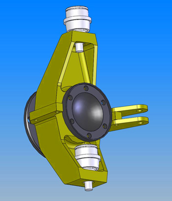
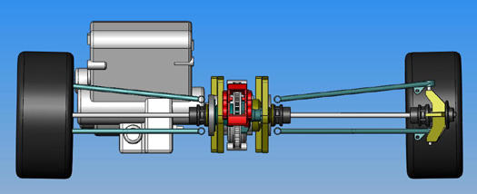
The steering 'arm' bracket can bolt on to either side, making this a universal part and allowing easy changes in steering geometry. According to my CAD system the upright should weigh 1.56 pounds if done in 7075 alloy. Steering tie-rods will use a 3/8" rod end for now, although the bracket setup allows changing to ATV tie-rod ends later. With a few more parts in CAD the design is looking kinda like this:
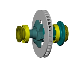
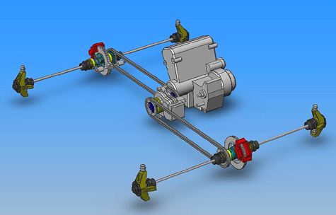
Having the driveshafts there gives it some sense of proportion and size. Keep in mind that the engine is not very big, occupying a roughly 20"x20"x20" cube. Alternatively, picture a motorcycle wrapped around the motor in the rendering above and it will give you a sense of the car's dimensions. 04/21/03 I've been spending some time on the design, finally, and things are moving along a bit. It's a pretty neat (though often frustrating) 3D puzzle and SolidWorks really helps put it all together. Being able to check interferences through full range of suspension and wheel motion is awesome, and spinning the whole thing around on the screen it is much easier to picture how to interconnect various components and what the tradeoffs are... I've gone through about a dozen suspension arm designs, three different concepts (so far) of how to mount the diffs and inboard suspension pickups, a couple of chain adjusting approaches, etc. The number of variables is mind-boggling. I'm also creating part numbers and entering them, along with calculated weights, into a spreadsheet. At the end of the process I should end up with a full BOM complete with weights, costs, descriptions and vendor contacts for each item. The suspension arms, despite their rather extreme 24" length, only weigh 1.93 lbs each according to the program. So I figure an even two pounds apiece. Overall I'm still within a couple pounds of my 700 lb target although that may change as I refine the details. So far my rough estimates for component weights have been pretty damn close.
There are quite a few aspects of the suspension design that are very experimental. Most of them are enabled by using AWD, inboard brakes and a backbone chassis. First, this allows very long control arms, as previously mentioned, and a near-vertical kingpin angle with less than 0.5" scrub radius. The purpose of this is to eliminate weird camber changes with steering and reduce torque forces since front wheels are also driven and power is significant for the weight. With +/- 2" of suspension travel this translates to less than +/- 5 degrees change in control arm (and halfshaft) angle. Because of that, I am able to use non-parallel, equal length upper and lower arms so all eight of them are identical - this should help with fabrication and spares. I can increase negative camber (and amount of camber gain with roll) by moving the inboard pickups of the upper control arms lower. There is no anti-dive or anti-squat in the geometry because the cross-corner antiroll bars should minimize both. Another goal of the suspension design is the raised position of the lower control arms, which combined with their length should create a lot of room for underbody tunnels. This should in turn generate plenty of downforce even at fairly tall (3-4") ride heights. So in theory it all works very nicely, and all the numbers come out very clean on the CAD system. How well it works in real life remains to be seen :)
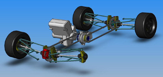
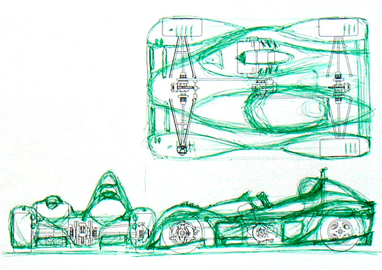
Also spent some time on the phone with Kodiak Motorsports who will most likely be making my wheels when I'm ready for that. The wheels are 13x8, and since I don't have any rotors inside them, they can be constructed from two 'outer' shells which reduces internal diameter. This makes tire changes much easier, makes the wheel stronger, lighter, and reduces rotational inertia. Due to the reduced internal clearance and the hub's location way inside the wheel, I have to pay particular attention to clearing suspension component when the wheels are turned, both in full droop and full compression. The steering angle is 20 degrees (limited equally by the CV joints and tie rod to wheel clearance), which due to the short wheelbase still gives an OK turning radius of 19.5 feet. Not spectacular for a car this small but better than the Westie (which is something like 27 feet) and similiar to the M Coupe. 04/22/03 Having grown a bit overwhelmed with the detail work, I decided to do something more conceptual/artsy for a bit. To that end, I plotted out a 3-view drawing of the components I have so far, and drew a body around them by hand, using my earlier concepts...
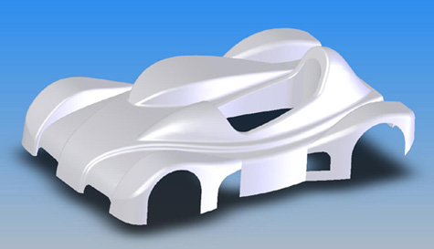
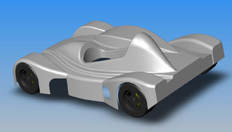
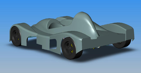
Ha. It seems like it's going to work quite well. The general idea is having a main 'body' as a thin airfoil, with 'bumps' for fenders, cockpit and engine. Overall I am trying to utilize the area rule of airplane aerodynamics. There is much argument over whether this supersonic concept applies to low-speed stuff, but there is evidence that it does. And it makes intuitive sense, too. The idea being that cross-sectional area of a body should change smoothly along its span. Any time you have an abrupt cross-section change, the air has to go somewhere and having no room to move aside it is being forced to abruptly accelerate (only to be decelrated later). This causes much drag and turbulence. The area rule is that if you have a bump on the body you should have an indentation next to it, and vice versa, so the air can move laterally and not get abused. The top view above speaks for itself. The main 'body', excluding bumps for fenders, cockpit and engine, is only 19" tall... :) The primary goal of the design is to move the air sideways and not vertically. Vertical movement generates lift which I want to aviod. Afterall, this is a 700 lb car with a design top speed of 170 mph (gearing limited). Additionally, there are some underbody tricks that I am contemplating (also shown above). I am trying to create as much tunnel volume as practical while keeping slopes gentle to prevent flow separation. Front tunnels vent to the side, underneath driver's raised feet. In the back, a low-mounted wing uses the gap between itself and the body to improve efficiency and assist the rear diffuser function. All this is accomplished with absolute minimum overhangs, placing front and rear low-pressure areas pretty much within the wheelbase. This greatly reduces pitch sensitivity and improves overall balance. Or so the theory says.... I already have an offer from someone to do wind-tunnel testing on a scale model next year. Hope he's serious and can't wait to take him up on that :) 04/24/03 It's been a long day but I did it. The initial CAD of the bodywork is done. Of course there will be much tweaking once more parts are finalized, and there's still a chance that I'll want to do it differently - but for now it's there. Also it looks like the whole shell should be doable as one single piece which simplifies things quite a bit.
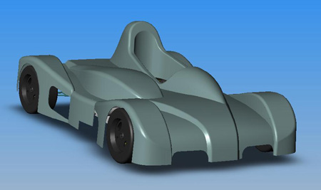
I've been staring at the screen all day, so now I've got to get some sleep. Whew.... 04/24/03 After waking up decided to clean up some lines that looked a little busy to me...
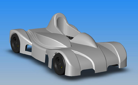
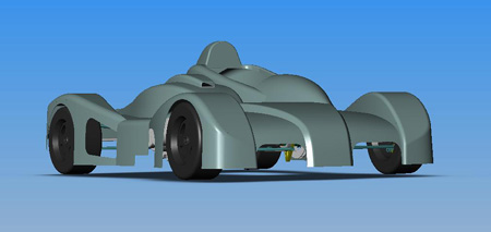
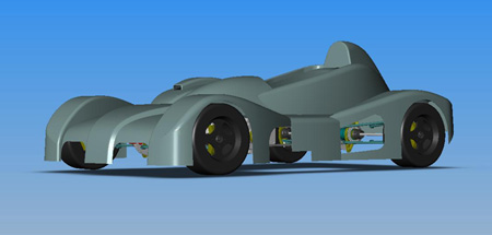
OK, I'm done tinkering with the bodywork for the moment. Need to take a break, maybe go work in the garage for a bit. The Westie is still in need of much maintenance and I've been neglecting it... 04/25/03 Something bothered me about the design, and an e-mail comment today helped me figure it out - the cockpit area was just not right. Since I was going to make changes I went through the SCCA rules for cockpit dimensions, rollcage and bracing. At present I don't intend to race the car, but would be nice to have the option. Plus those regulations are there for safety so it is really a wise thing to take advantage of them. With that in mind I redesigned the area around the driver and besides being safer I think it looks better now, too. With a 1.0L engine (from a GSXR1000) the car should be eligible for DSR competition.
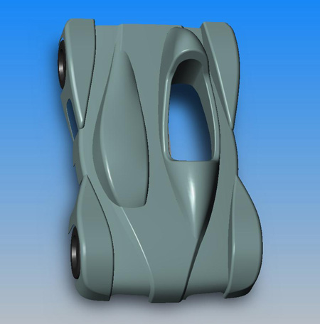
Of course more tweaking will have to be done as the design evolves. I'm also learning more about using SolidWorks, which is a useful skill to have. The bodywork really makes it look like a car rather than the collection of parts I had before. This is probably why it feels like such huge progress even though the body design only took 3 days so far. That is also probably why I keep posting all the pictures :) Sometimes I just sit and spin the car on the screen in 3D - this is where my investment in a 3GHz machine and a huge LCD monitor is really paying off! I'll get over it, of course, but for now I'm pretty excited. In other news, got word today that the machining of the halfshafts is complete and they should be showing up in a few days. No word yet on the differentials. For the moment I have a lot more design work to do so it's not really holding me up. |