|
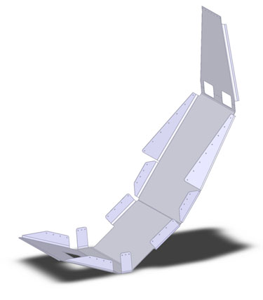
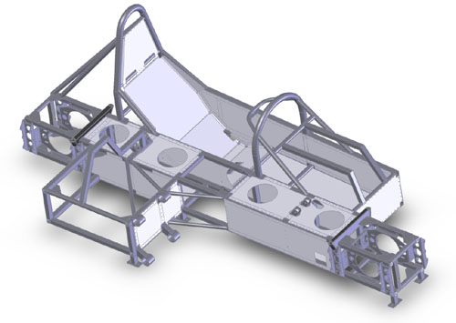
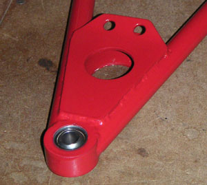
04/14/05 For the last few days I've been working on the sheetmetal panels for the frame. It really reminded me of why I'd been dreading this part - it's a lot of fiddly work, nothing is simple but everything is connected (and needs to be accessed!). To make it more fun, there are countless different ways of doing the same thing, all with their own consequences that don't always become clear until you've done a bunch of other work. I have gone through literally dozens of iterations, sometimes redoing the same parts four or five times from scratch. How hard can it be, right? Not really hard, just a pain. The seat tray below is an illustration:
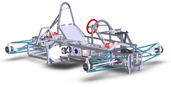
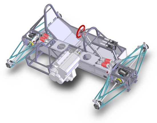
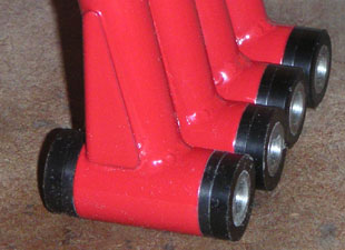
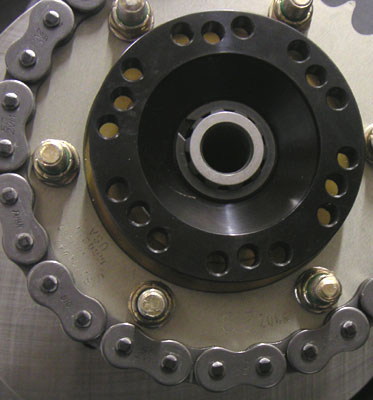
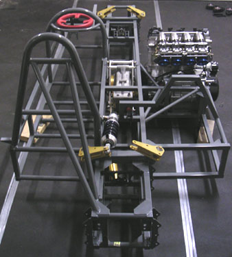
Yes, there's a reason for every cut and fold. And yes, almost all of them could be done differently. In fact, if it proves to be expensive to make this way I might just buy a carbon seat and install it instead. Decisions, decisions. On the definitive progress side, I finally figured out how I'm going to do chain management. The challenge is to constrain the chain vertically and laterally without undue wear or friction. It also needs to be reasonably cheap and provide a safe place for the chain to go if it were to break, without mangling things in the process. So I came up with little guides machined out of nylon or similar material. Granted, I'll need 20 of them but they should work quite well and hopefully won't be too expensive. They are the red bits in the chassis picture below (I haven't come up with a good way to show them in place but they fit well with the paneling and everything else).
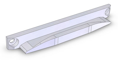
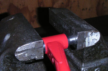
So basically I've been messing in the virtual domain after working in the physical one for a while. It's kind of interesting to alternate between the two and then see parts migrate from the screen to the shop. Every time that transition takes place successfully I marvel at the tools that are at my disposal these days - and the fact that many if not most of the all-time great cars were built without, using just chalklines on the shop floor and a tree stump out back. I keep coming back to this - there's more than one way to do things. I like my way :) 04/18/05 When designing the chain guides I wasn't quite sure what material to use so my secret hope had been that by posting about it I'd prompt someone to write in with a suggestion. Sure enough, three people did (thank you gentlemen :) all saying the same thing - UHMW polyethylene. Upon checking the material properties I totally agree. Great stuff and cheap too. It will also get used for 'rub strips' on the bottom of the floor. So here's an illustration of what I mean by there being more than one way to do things: I spent more time thinking about the chain guards, now that I knew what I'll be making them out of, and came up with a totally different design.
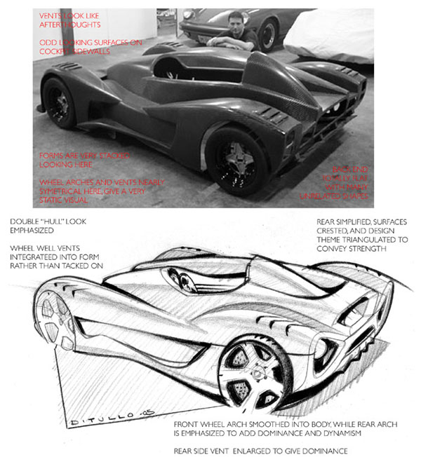
This completely encloses the chain (eliminating the mess of lubricant spraying everywhere) and gives it a place to go in the event it might break. What may not be totally apparent in the picture is a slot to feed the chain in for installation/removal and a spot to give access for breaker/riveting tool. Gotta think of such stuff. This will most likely be the design I go with, I'll have comparative pricing tomorrow. My vendor's comment was 'wow, this changed some'. Indeed. On a whole different topic, occasionally someone writes me pointing to a discussion of the dp1 on one forum or another. Sometimes I go and make a comment or two, other times not. This particular thread was on a design forum and aside from the typical remarks on how good it must be to be idle rich (I am very far from either, just for the record!) there were some comments on the styling that I wanted to discuss. Typically when I challenge people with opinions to do better they just go away, but in this case I got a very nice sketch (and hopefully a few more to come) from Michael DiTullo - who purely coincidentally happens to be based here in Portland. Small world.
Some points well taken (see my comments in the thread with regard to how design sketches relate to actual parts you can make for a caveat or two). Not that I'm going to change anything in the bodywork at this stage but interesting to see ideas from different people and I'll definitely keep the feedback in mind for my next design. That's how one learns, right? :) Perhaps we might even collaborate on a few things in the future... 04/20/05 Well, the design of the chassis panels is almost complete. As with just about every part of the car, these have gone through a half-dozen revisions each and will still be tweaked some as I contemplate accessibility, assembly steps, etc.
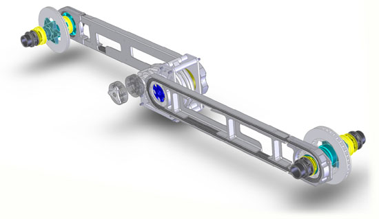
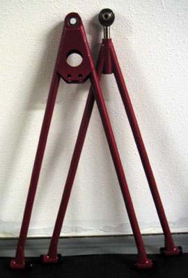
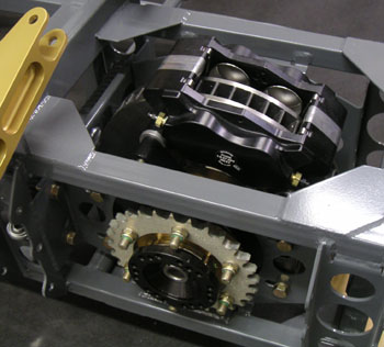
And yes, the center diff assembly is structural and is mounted in heavy-duty steel flanges with close-tolerance bolts custom machined for the purpose, so the 'discontinuity' of the chassis torsion box is not an issue. Is the chassis as stiff as it could possibly be? No. But for the purposes of prototype proof of concept and test platform it'll do. Am I going to measure its stiffness? No. Am I concerned about it? No. There are plenty of other things to worry about. After the panels go off for manufacture, shifter design is next. That should be pretty clean and hopefully fun. Also, anti-roll bars are already designed in principle but I still need to do the calcs for sizing and then model the remaining parts... They'll be of conventional type, the diagonal setup will have to wait till later (it can be retrofitted, at least in theory). 04/23/05 The word for the day - BEARINGS. And clearances. Put together the suspension arms today. The bushings were specced at 0.003" over OD and on the spot for ID (0.625"). The people who made them suggested there should be some interference, so I said OK, just make the stuff fit. The result was busihing ID of 0.620". The catch is that when you press those into a 0.875" bore (the busings being 0.878" OD) they tend to compress a bit. So while it was possible to press the bearing sleeve into the bushings, there was no way it was going to serve as any kind of a pivot. Luckily I was able to find a 0.625" drill bit and running it through the bushings once installed resulted in a 0.624" bore due to material spring-back. Just about perfect.
The last picture shows the shim stack to implement the 5 degree caster upfront... Of course the shims were not perfect, my mistake at this point by 0.032" so I had to do a bit of sanding. Make that quite a bit actually. But all is well that ends well.
On the less-well note, the spherical bearings once pressed into the lower A-arm bores ended up too tight. The bores were specced and made per recommendations but I really have to wonder here - we're talking on the order of 10 lb-ft breaking torque. Anyone have any suggestions? In production I'll just use swaged bearings and a different design, but I wonder if the prototype ones will loosen up over time or if I should do something about it... Another rather embarassing point is that the retaining rings for the bearings are 0.100" off. Looking at CAD that's exactly how it is. Brain fade on my part I guess... Fixable with spacers.
Along the same lines, the steering column had 0.010" taken off it when the welds were cleaned up for the bearing. Meaning the stuff is now too loose and I have to re-make the bearing piece. So it goes. On the plus side, I checked the clearance of the chain to the sprocket bolts and it does in fact clear. Just... Like it's supposed to.
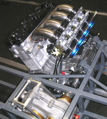
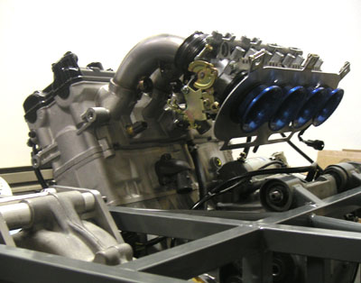
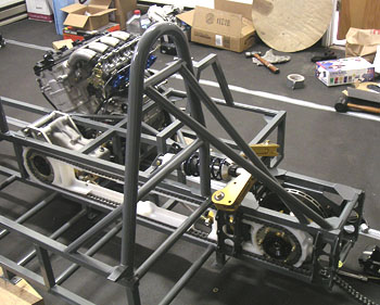
Live and learn. Wish education were a bit cheaper... :) 05/09/05 While waiting for the aluminum panels to get made I've been tinkering with other bits. Most significant is the test-fitting of the engine and the intake manifold that I just picked up from Super 7 Cars. The intake lowers the overall profile of the installation and bumps low-end torque a bit which is a good thing.
The engine installation itself has a couple glitches. First, I neglected to model a protrusion on the alternator cover in SolidWorks so while the engine fits fine in CAD, in real life the protrusion interferes with a frame tube. So I had to hammer the tube in a bit - low-tech solution to a high-tech oversight. The other issue is that the front of the engine hangs about 1/2" too low. I'm not sure what the cause of this is but there are several possible solutions, ranging from shimming the floor down 1/4" to using eccentric bushings in top mounts. Disappointing but workable. On the plus side, the driveshaft between the engine and center diff lines up perfectly, both in terms of position and length.
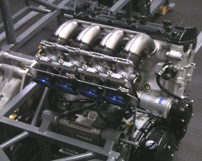
With the engine in the chassis looks just a little bit closer to completion. One day....
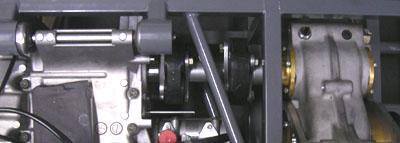
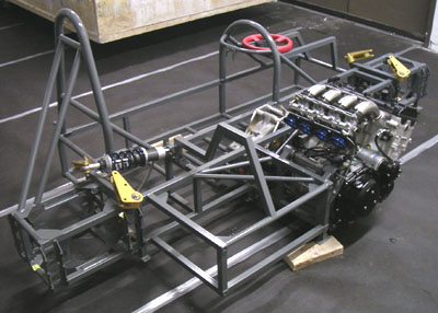
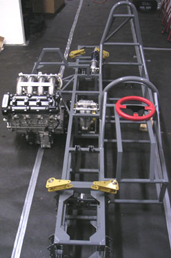
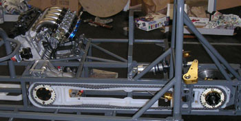
In the meantime, the items that remain to be designed are gas pedal, shifter and exhaust. Then they'll need to be fabricated. The rest is just assembly, fitting and testing. Yes, a number of internal body panels such as fender liners still have to be made but they'll come after the car runs and has at least a few miles on it. First runs will be made without bodywork. 05/12/05 Some more test-fitting, this time of diffs and brakes. Overall things fit pretty well with the exception of a glitch in alignment of chain tensioning bolt and diff carrier bracket. Checking the SolidWorks file shows that the parts were made exactly as designed so the glitch was in my head. Should have looked closer at the assembly. I think it was a dimension I had changed during one of the countless design iterations but obviously didn't update all the parts. More education, I guess - at least the parts are not very expensive and can be easily made with new dims.
In the meantime, the effort by Michael DiTullo and Wyatt Turner to design an alternative dp1 body continues with some good progress - see thread on Core77. (pic below courtesy Wyatt Turner).
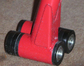
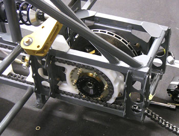
When Michael and I were discussing the possibility of doing this we talked about how in the early days people would buy a chassis from a manufacturer then commission coachwork from a different company. These days unibody designs make that impractical but the dp1 lends itself very well to the custom coachwork concept. The body is one piece and can be replaced in about 10 minutes so it's conceivable that someone would have several different bodies for a car and change them as the mood or occasion dictates. I hope this effort (code named dpX) comes to fruition - would be cool to give customers several choices for bodywork. I don't have time/resources to dedicate to this myself so it's great to see other people getting together to do it. 05/14/05 Got the chain guards and test-fit those. A few minor interference issues with bolts and brackets, all my oversights, but easy to fix and overall these should work. At least for the prototype.
In theory, the chain guards should limit chain motion both laterally and vertically, hopefully reducing wear on chain and sprockets. I wonder how noisy this setup is going to be and how well it'll stand up to wear. I've not seen anyone do it this way and I think it's because sprockets are usually not stationary with respect to each other - but maybe there's another reason. Yet another experiment. If it works well, I will have discovered something useful. Actually, I will have discovered something either way. That's what this whole project is about - to learn things. |