|
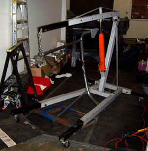
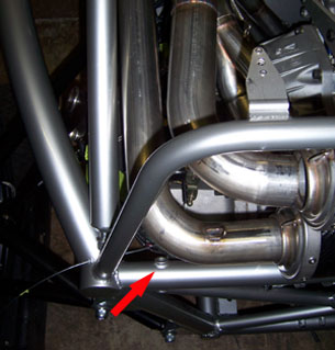
12/01/06 I've been getting some very good advice on heat shielding options - many thanks to all who wrote with suggestions. I'm now sorting through all the available ways of tackling this and will decide on the most useful combination shortly. One definite part of the equation is ceramic coating of the exhaust. To that end I removed all the pipes and took them to Brooks Performance Coating. Should be done in a couple of weeks. Prior to removing the exhaust I took a stab at finding a fix for the rollbar interference problem. The most obvious is to simply bend the bracing tubes outward to clear the exhaust and find a new way to anchor them to the frame. So that's what I did. With some very helpful input from Joe I ended up using an engine hoist to spread the ends of the tubes apart from 28.5" to 34.5". The improvised rig can be seen below, along with the approximate fit of the modified rollbar.
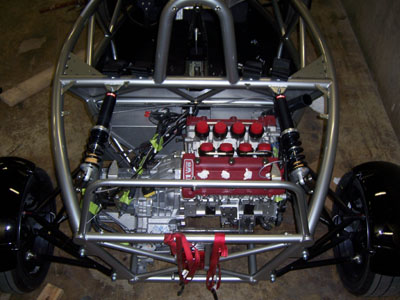
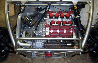
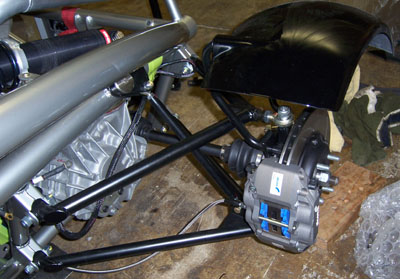
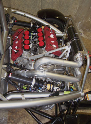
The red arrow in the middle picture shows the original anchor point so you can see how much the tubes had to be moved. I already have a new mounting scheme in mind that should be strong enough for safety. Of course welding brackets to the tubes will ruin the powdercoat but I was thinking of redoing the bar in black anyway - it looks a little bulky in silver and the black will hide it a bit and will match the suspension nicely. Another item was attaching the intermediate shaft support bracket - the first one that we had made caused the bearing flange to interfere with the exhaust. The new one fits perfectly, with at least a quarter inch to spare - very typical of the clearances here. Without the exhaust in the way you can see how compact the V8 is.
Things are moving forward but the list remains very long. This is when winter weather is good - it removes some of the stress by granting me about 3 months to get things done. Should be just about right. Also, work is progressing on the dp1 but not enough for an update yet. 12/03/06 A week ago I started my in-head simulator on the task of coming up with a solution to the gastank-exhaust clearance issue. After spinning things around in 3D in countless variations at random moments, a solution popped out - move the tank down a bit, which will also move it forward. A few things would need to be tweaked but should be doable. So I went to the shop and did exactly that. In the first picture it can be seen that the coolant and oil cooler tubes run under the tank so they'd have to be cut and routed over the top. This neatly solves another major challenge that I was facing, namely the routing of all the hoses around the exhaust.
With the tubes cut I was able to drop the tank about an inch (the frame tubes prevent it from going lower). This moved the tank forward about 3/4" and created enough room in the existing clearance 'pocket' on top for the hoses. Of course I still have to do shielding but this simplifies things considerably.
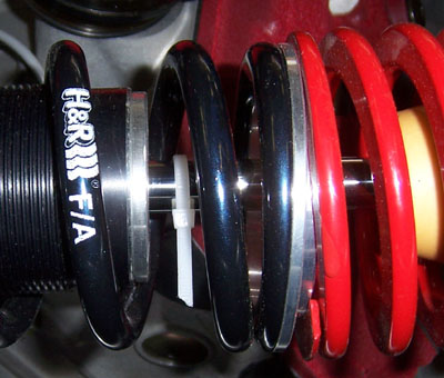
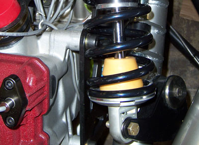
While I had the car jacked up I also checked rear shock travel. It was rather surprising to find that at full droop the shock only extended 1/4". The wheels dropped 5/8" which is another unexpected find. A quick measurement of the suspension pickup points and the bellcrank shows that the motion ratio should be very close to 1, i.e. for every inch of wheel travel the shock should move an inch. But the effective ratio ends up being about 0.5 which is probably due to the angles in the bellcrank. I'll have to take a closer look at that. Also, the helper springs are the same rate as the main ones in the back (40N/mm for both). On the front the main/helper set is 30/25. Given the ratios and the minimal travel in droop there's really no point in having the two-spring setup, it's just extra weight and can cause problems with deflection (notice the helper spring is not seated properly in the picture, two of them are like this on the car and they don't snap into place when the car is sitting on its wheels). My guess is that they are there just for cosmetics and they do look neat, but on my car they're coming off. I'm also going to try and turn the shocks around so that the shock body does not move with the wheel. This would remove about 5 lb unsprung weight per corner. There might be an issue with clearance of the spring though, so I'm not certain that this is doable. We'll see.
12/04/06 Finished bolting the fuel tank in the new location, then messed with the suspension some. One thing I did is measure the front shock travel and re-measured the rear as well. Turns out I must have been mistaken earlier because both front and rear are about 1.0 motion ratio, which is good. Next I took the helper springs off and swapped to 50N/mm rear springs (from 40). The fronts are still 30N/mm. this should better match the weight distribution and provide some more roll stiffness in the back, where all the heavy stuff is. We'll see how this works, I can change to 40/60 later. I reinstalled the shocks with the body on the sprung side. Definitely doesn't look as jazzy as the stock setup but should work a little better, at least in theory.
Doing the same in the back poses a bit of a clearance issue with one of the engine mount bolts. I may try and get a low-profile buttonhead bolt. Or it may just be more trouble than it's worth - I doubt that the difference between mounting the shocks one way vs. the other would really be noticeable. It's more of a conceptual 'purist' thing to me :)
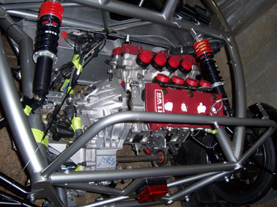
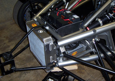
Several people asked if I thought the radiator was going to handle the V8 cooling needs. An owner of a UK Atom who lives in a warm climate mentioned that his radiator was inadequate even for the Honda 4-cylinder when ambient temperature was high. The Brammo setup is supposed to handle the 300hp GM mill and looking at the actual pieces it looks like it should have plenty of capacity. The main radiator is a thick, dual-pass design. Behind it, sitting horizontally, is another radiator that Brammo uses as an intercooler for the supercharger system. I'm using it to cool the oil. Like in the dp1, scavenged oil from the drysump is pumped through the cooler and then goes into the oil tank. There is very little pressure in the system, basically just whatever is there from the resistance of the lines and the radiator core. This is why I can use a radiator and don't need a heavy-duty oil cooler.
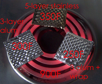
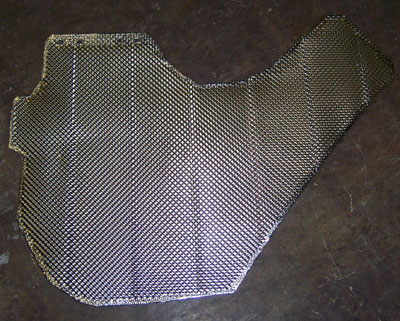
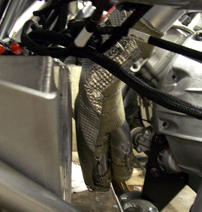
12/07/06 Work continues. Did some CAD to check clearances then ordered a drysump oil tank, an electric water pump, a fuel pressure regulator and some plumbing bits. Another thousand bucks disappears just like that. Well, children are expensive. Even the non-biological kind. Made good progress though. I received a great number of suggestions and leads on the heat shielding issue - many thanks to everyone who took the time to write. Some I'm still pursuing, but of particular interest was an email exchange with Lee Demory. Lee works for a company that supplies shielding solutions to the big carmakers. They use multi-layer corrugated sheetmetal, either stainless or aluminum depending on application. After providing some very good input he was kind enough to send me a box of the stuff so today I decided to experiment with it a bit. Now, granted, the setup is very non-scientific, for a number of reasons. But basically I made up some small samples of the material and used a household electric stove and an IR thermometer to get a rough measure of what I'm looking at (yes, I actually got to use the stove for maybe the third time in 8 years).
The three samples, shown above, are 5-layer stainless material, 3-layer aluminum material and the same aluminum material sitting on top of two strips of exhaust wrap (yes, it smelled a bit at first). There are several reasons why this is not a very scientific test. First, the samples are very small in size and the edges are hemmed, so conduction plays a bigger role than it normally would. Second (and perhaps more importantly) the IR thermometer is not the best tool for this. The readings varied quite a bit with angle and position so the numbers represent the best average. Yes, I know, I should get a good thermocouple setup. Eventually. The IR device I just borrowed from my friend Roy so it was free and quick (he even bought me lunch, not quite sure how that worked out but hey, I'll take it - THANKS!). Anyway, the numbers in the picture tell the tale. Just like Lee said, aluminum performs better - that is, until the piece on the left spontaneously melted into nothing! It was more fun to watch than to clean up. The piece sitting on top of the exhaust wrap survived and worked best of all. When I later placed the stainless on top of the wrap (after scraping the melted aluminum off with a fork - high tech, and it IS the kitchen afterall!), its temperature dropped by roughly 50F. So putting the wrap under the shield is definitely beneficial. Just in case the thermometer was misleading me, I verified the results by trying to hold my finger about 1/8" off the surface in different spots. The unshielded heater element was unbearable even at 1/2" for less than a second so that sets the baseline. The shielded bits, when I was careful to approach them so that I wouldn't get burned on the open element, roughly confirmed the readings. It was not a problem to hold finger at 1/8" above aluminum+wrap for over 30 seconds which is about my span of attention. The un-insulated aluminum (prior to melting) was noticably hotter and the stainless was the hottest of the bunch but still bearable for a bit. So there you have it. Based on the results I decided to make a quick aluminum shield for the dp1 exhaust where it sits close to the carbon bodywork above it. Since the thing goes over the top of essentially two layers of exhaust wrap (and it's pretty far downstream), I figured it should live. Time will tell.
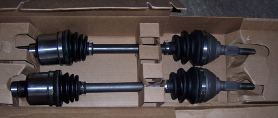
In other news, the halfshafts finally showed up. I'll install them in a couple of days.
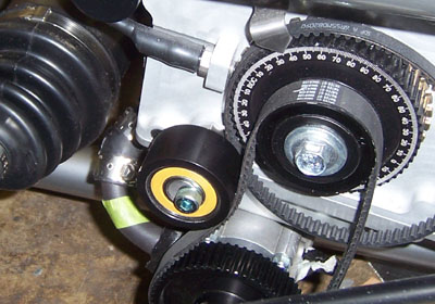
I'm now messing with the oil pump, plumbing and the like. Fun stuff. When all the pieces are in I'll make an assessment of where I'm at and go from there. Hope the halfshafts fit. As I'm fond of saying - 'nevermind the path less traveled, I make my own' ;) Onward. 12/13/06 Good progress today. The drysump pump was one of the tightest clearances, with about 1/16" between a frame rail and one of the mounting bolts. So today I counter-bored the mounting holes and removed some spacing shims from between the pump and the sump. The result is a generous 1/4" clearance - this should do fine. Of course removing the shims made it impossible to adjust the belt because the adjuster is out of range and there is no shorter belt available. After a consultation with John we decided that he'll make a sleeve for the idler, increasing its diameter by 1/2". I'll press it on and that should do the trick.
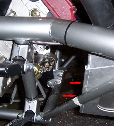
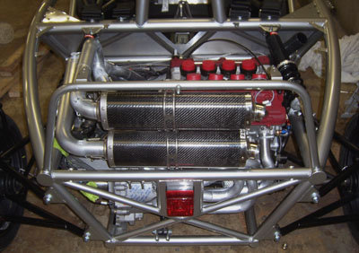
The picture above also shows the clearance between an oil scavenge tube and the CV joint. Yep, a bit less than 1/4" but it should do. Speaking of CV joints, the driveshafts went it without issues. the driver-side one required a bit more work to get it in but overall they fit well. Whew. The second picture also shows the massive Alcon rear brakes. According to Brammo, brakes work best with bias set almost equally front-to-rear. Considering that 60% of the car's weight is on the back it is not too surprising, actually. One benefit of rear weight bias is that rear brakes get to do more of their share of the work and overall braking performance is improved.
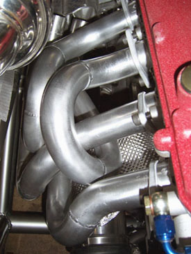
The exhaust is back from ceramic coating and looks good. I'm doing the installation in steps. Due to tight slip fits I'm having to remove the coating on tube ends which takes a while, this is why I don't do it all at once. All the sanding kills the fingers too. Of course I was expecting it so it's not a complaint. I could have had the pipes opened up a bit to allow for the coating but it's not a precise process and I opted for just doing the sanding. Since the tubes are stainless steel the loss of coating does not carry any corrosion or durability risk, as it would with mild steel tubing. With the tank moved forward there's all kinds of room now. I already did the wrap on selected portions of the headers. Fabrication of the shielding is next. I'm waiting for a thermocouple to be delivered so I can put it on the tank under the shielding to enable me to check the tank temperature in operation. Should be here in a couple of days. Starter solenoid clerance is still an issue though. I'm evaluating possible solutions.
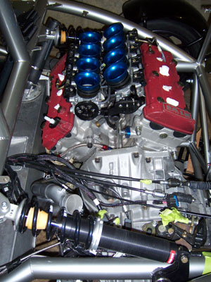
Also did a test-fit of the throttle bodies. No apparent clearance issues, which is good. I'll have the throttle linkage on the other side in final assembly. Putting it towards the center seemed to make sense until I checked the cable routing. Now I'm certain the other way will be better. Some may notice I flipped the rear shocks back around. This is because apparently M10-1.25 bolts don't exist in buttonhead configuration, which is what I'd need to clear the spring on the right-side shock. I haven't fully given up yet but for now this is how it is. I would still prefer to run the shocks facing the other way, especially since it would give more clearance to the exhaust on the left. If anyone knows of a source for the buttonhead bolts in M10 fine 1.25 thread (30mm or 35mm length), let me know.
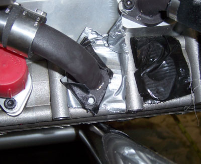
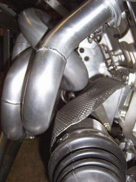
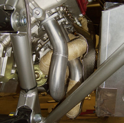
12/14/06 Got things taken care of with the DMV today, now just waiting for the plates to show up. Not that I'll be driving the car anytime soon. Even if I had it finished, it's just not Bikini weather for the next couple months. Work-wise, finished prepping the exhaust and fabricated a heatshield for the intermediate support bearing and CV joint. This one is aluminum and I think it's far enough from the pipes (about 1/2") that it should be fine. If it starts deteriorating I can always re-do it in stainless.
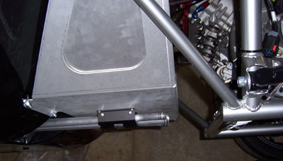
Thanks to everyone who wrote with suggestions on buttonhead bolts. It seems they only come in chrome (at $9 apiece) and titanium (at $8 apiece). I have tried contacting the vendor of the titanium ones but no response so far. We'll see. As best I can tell the chrome variety are accessories for Yamaha cruiser bikes. Therefore the factory probably uses less-flashy versions of the same thing so perhaps a visit to a Yamaha dealer might be worthwhile. 12/15/06 Got the thermocouple and installed it on the gas tank directly opposite the closest exhaust bend. This way I'll be able to see how hot the tank itself is getting.
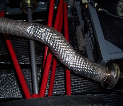
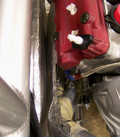
After the thermocouple I added the aluminum shielding to the tank (with an insulating layer under it) and then fabricated and installed the stainless shield on the exhaust.
After all the insulation there is still a 1/2" gap between the two sides so hopefully this should do it. We'll see. The engine bay is looking more crowded every day. And yes, the shocks are turned around once again. I'm just going to have to find a buttonhead bolt somewhere.
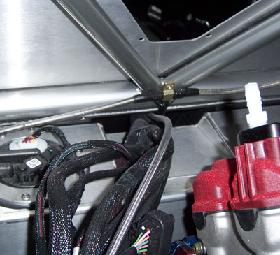
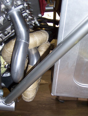
It's rather neat how the exhaust pipes follow the contour of the chassis rail. Works for me :)
|